background image

a-1

Appendix A : Standard Source Set Up Files

5975948 RETRODATA 2100 210198

A

Standard preprogrammed set up files

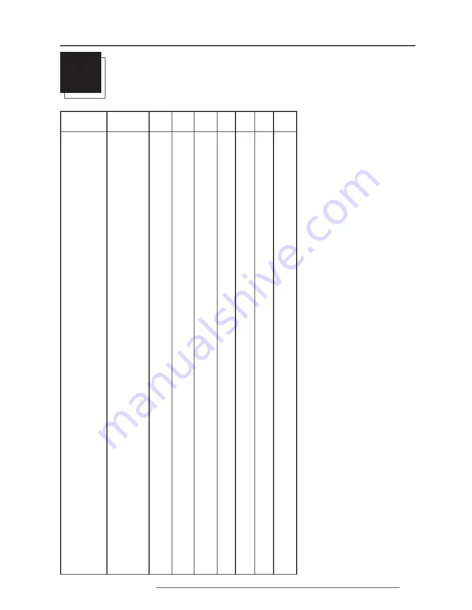
 STANDARD SOURCE SET UP FILES

Name :

 name of file, contains the settings

Resolution : image resolution, when followed

by ...I means interlaced.

FVERT Hz :

 vertical frequency of the source

FHOR kHz :

 horizontal frequency of the

source.

FPIX MHz :

 pixel frequency

PTOT :

 total pixels on one horizontal line

PACT :

 active pixels on one horizontal line

LTOT :

  total lines in one frame

LACT :

 active lines in one frame

NAME

RESOLUTION FVERT FHOR

FPIX

PTOT PACT LTOT LACT

Hz

kHz

MHz

CGA

640 X 200

59,924 15,700 14,318 912

640

262

200

NTSC

675 X 240I

29,970 15,734 13,500 858

720

263

240

PAL

675 X 278I

25,000 15,625 13,500 864

720

313

278

SECAM

675 X 278I

25,000 15,625 13,500 864

720

313

278

EGA

640 X 350

59,702 21,851 16,257 744

640

366

350

MAC_5

512 X 342

60,158 22,259 15,670 704

512

370

342

MAC_3

512 X 384

60,147 24,480 15,667 640

512

407

384

MAC_4

560 X 384

60,147 24,480 17,234 704

560

407

384

8514-A

1024 X 384I

43,479 35,522 44,900 1264 1024 409

384

VGA_TXT

720 X 400

70,087 31,469 28,322 900

720

449

400

COMPUSC4 1024 X 480I

29,945 30,694 39,779 1296 1024 512

480

VGA_72V

640 X 480

72,800 37,856 31,496 832

640

520

480

VGA_GR

640 X 480

59,941 31,469 25,175 800

640

525

480

VGA75ISO 640 X 480

75,000 39,375 31,500 800

640

525

480

MAC_2

640 X 480

66,667 35,000 30,240 864

640

525

480

MAC_LC

640 X 480

66,619 34,975 31,338 896

640

525

480

MUSE

960 X 518I

30,000 33,750 37,125 1100 960

563

518

HDMAC

1008 X 570I

25,020 31,250 39,125 1252 1008 625

570

SVGA_56V 800 X 600

56,250 35,156 36,000 1024 800

625

600

SVGA_60V 800 X 600

60,317 37,879 40,000 1056 800

628

600

SVGA_72V 800 X 600

72,084 48,080 50,003 1040 800

667

600

XGA_70V

1024 X 768

69,705 56,182 74,610 1328 1024 806

768

XGA_60

1024 X 768

60,000 48,360 64,996 1344 1024 806

768

XGA_75

1024 X 768

75,781 61,080 86,000 1408 1024 806

768

XGA_72

1024 X 768

71,955 58,140 80,000 1376 1024 808

768

SUP_MAC

1024 X 768

60,000 48,780 63,999 1312 1024 813

768

XGA_70

1024 X 768

70,000 57,050 78,044 1368 1024 815

768

MAC_POR

640 X 870

74,996 68,846 57,280 832

640

918

870

SG_60_2

1024 X 768

60,000 48.780 64,390 1320 1024 812

768

SG_60_3

960 X 680

60,000 43,200 54,432 1260 960

720

680

Summary of Contents for R9001300

Page 1: ...OWNER S MANUAL RETRO DATA 2100 R9001300...

Page 2: ...BARCO PROJECTION SYSTEMS Date 260898 Rev02 OWNER S MANUAL R9001300 RETRO DATA 2100 Art No R5975948...

Page 3: ...51 E mail sales bps barco com Visit Barco at the web http www barco com Printed in Belgium Due to constant research the information in this manual is subject to change without notice Produced by BARCO...

Page 4: ...tion to the projector 4 1 Connecting a Video source to the Video in 2 input 4 1 Connecting a Audio source to the Audio in B input 4 1 Connecting a RGB source to the RGB in 4 input 4 2 Rear Input conne...

Page 5: ...eometry 8 9 Shift 8 9 Size 8 10 Zoom 8 10 Blanking 8 11 Scale 8 12 INSTALLATION MODE 9 Starting up the Installation Mode 9 1 Configuration 9 1 Internal Patterns 9 2 SERVICE MODE 10 Starting up the Ser...

Page 6: ...tect the user or operator against risk of electric shock and energy hazard and having access to live parts Safety standards also impose limits to the internal and external temperature rises radiation...

Page 7: ...plug is damaged or frayed b If liquid has been spilled into the equipment c If the product has been exposed to rain or water d If the product does not operate normally when the operating instructions...

Page 8: ...l Description and Function Gaining access to the front control panel To reveal the keyboard in the front portion of the retro projector push with one finger on the indicated place of the keyboard door...

Page 9: ...ds when in the adjustment mode 12 Control disc To make menu selections when in the adjustment mode Also allows to increment or decrement an adjustment in the adjustment mode Control disc up up arrow i...

Page 10: ...IO IN A B C or AUDIO OUT are selected 19 Audio In 3 audio inputs on 2 Cinch RCA connectors for audio L R Audio B is a fixed wire input not to be interchanged 20 Lens Mounting Projected picture output...

Page 11: ...XT is off no warning message will be displayed 13 FREEZ To freeze the projected image the picture will freeze but the sound will continue 14 ENTER To start up the adjustment mode or to confirm an adju...

Page 12: ...he same type of fuse refer replacement to qualified service personnel Fuse type T16AH 250V Order no B370076 AC Power mains Cord Connection Ensure that the power switch is in the on 1 position on the r...

Page 13: ...switching on with the power switch the projector starts in the stand by mode The projector mode status LED lamp is red FRONT CONTROL PANEL 0 9 7 8 6 5 4 3 2 1 BALANCE VOLUME BASS CONTRAST TREBLE BRIG...

Page 14: ...button 2 on the RCU Front Input Connections Signal input connections to the projector 1 Connecting a Video source to the Video in 2 input 2 Connecting a Audio source to the Audio in B input 3 Connecti...

Page 15: ...de Connect the possible audio input signals for port 4 to the AUDIO B input when the audio lock is OFF see also chapter Controlling RGB input selection For port 4 press digit button 4 on the RCU If th...

Page 16: ...al loud speakers front input sockets 2 Connecting a S Video source to the 4 mini DIN input port 3 Separate Y luma C chroma signals for higher quality playback of Super VHS signals 1 x 4 pins plug pin...

Page 17: ...V R9828059 Order number 230V R9828050 MAGIK interface Order number 120V R9828129 Order number 230V R9828120 RGBS RGsB analog 5 x BNC Red 0 7 Vpp 3 dB Blue 0 7 Vpp 3 dB Green 0 7 Vpp 3 dB 1 Vpp 3 dB if...

Page 18: ...765 Peripheral Equipment Input Connections 1 Connecting a computer 2 Connecting a RCVDS05 3 Connecting a VS05 4 Connecting an IR Remote Receiver 800 WARNING POWER DOWN ALL DEVICES BEFORE STARTING CONN...

Page 19: ...e projector can be of standard or HDTV frequency in case of HDTV compatible projec tors or Component Video for projectors with Component Video input Connect the audio output to the default input AUDIO...

Page 20: ...tic cover insert the card for RCU You can cut out the insert cards in appendix C of this manual Battery installation in the RCU How to use the RCU Projector address Picture controls with direct access...

Page 21: ...U it is necessary to enter the projector address into the RCU only when that address is between 1 and 9 The projector with the corresponding address will listen to that specific RCU When address 0 zer...

Page 22: ...visual indication on the screen of the current contrast setting while pressing the or buttons RCU If the bar scale is not visible on the screen press TEXT key once and retry the above indicated keys T...

Page 23: ...when pressing the button redder flesh tones SharpnessControl Sharpness control is only active for Video and S Video Inputs A bar scale gives a visual indication on the screen of the current sharpness...

Page 24: ...ation on the screen of the current treble level while pressing on the or buttons The bar scale and numeric indicator increase to the right when pressing the button higher treble reproduction and incre...

Page 25: ...Balance control Adjust the balance with the and button until the desired balance is obtained When TEXT is on a bar scale and a indicator below the bar scale between L and R give a visual indication o...

Page 26: ...When your password is wrong The error message Invalid pass word is displayed on the screen Press ENTER to continue and to return to the Service menu Factory programmed password 0 0 0 0 Once the passwo...

Page 27: ...with or then ENTER EXIT to return Select with or then ENTER EXIT to return Starting up the Random Access Adjustment Mode RANDOM ACCESS ADJUSTMENT MODE FILE SERVICE PICTURE TUNING AUDIO TUNING GEOMETR...

Page 28: ...n brackets Load file Press the control disc forwards or backwards to select LOAD and press ENTER to display the Load menu The Load menu displays the corresponding files depending on the installed filt...

Page 29: ...f the active file select Horizontal or Vertical by pushing the control disc forwards or backwards and then press ENTER A full image is displayed with the settings on the left side To change the values...

Page 30: ...tions Source number The source number of a non active source can be changed to any other source number This makes it possible to create already a file for future source numbers Clamp pulse width The w...

Page 31: ...sc forwards or backwards Numeric characters can be entered directly with numeric keys on the RCU Press ENTER to confirm The copied file is entered in the list of files Press EXIT to return to the Copy...

Page 32: ...l be displayed The next items are available Sync Slow Fast Still Video Color Balance Gamma Press ENTER to toggle between name and index name The files in the file list will be sorted on the file name...

Page 33: ...st red and push the control disc to the right or to the left to adjust blue range 0 to 2 5 in comparison with the green color value 1 Pressing the control disc forwards or backwards to select Fixed Co...

Page 34: ...th a bar scale icon and function name of the control e g Volume appears on the screen only when text is ON The length of the bar scale indicates the current memorized setting for this source For more...

Page 35: ...ertical image size Zoom Blanking Scale 1 1 Fade Select Fade by pressing the control disc forwards or backwards The fade can be adjusted between 15 and 15 Fade on 15 no sound reproduction on the extern...

Page 36: ...ay Pressing the control disc to the right or to the left for a vertical re sizing push the control disc forwards or backwards for a horizon tal re sizing The default value for both directions on the b...

Page 37: ...BOTTOM LEFT RIGHT RESET The Blanking can be switched ON or OFF Select Blanking xx by pressing the control disc forwards or backwards and press ENTER to toggle between ON or OFF When OFF the image is...

Page 38: ...ll be lost If the source signal contains less pixels only part of the screen will be filled Press ENTER to toggle scale between 1 1 and 1 x When toggled to 1 x the full image will be displayed Note Wh...

Page 39: ...outline color bars multi burst checker board purity Select with or then ENTER EXIT to return ADJUSTMENT MODE Select a path from below RANDOM ACCESS INSTALLATION SERVICE Source 01 INSTALLATION CONFIGUR...

Page 40: ...rnal patterns which can be used for measurement purposes Highlight Internal Patterns by pressing the control disc forwards or backwards and press ENTER to display the Internal Pattern selection menu T...

Page 41: ...e control disc and press ENTER to display the other items in the service menu Select with or then ENTER EXIT to return ENTER continues to the Service mode selection menu EXIT returns to operational mo...

Page 42: ...RUNTIME HISTORY Serial No Runtime 0111121 600 h 0110031 750 h 0110010 745 h EXIT to return PRESET INPUT BALANCE FILTER XGA BLACK BALANCE WHITE BALANCE Select with or then ENTER adjust red with or blue...

Page 43: ...authorised BARCO service centre Select with or then ENTER EXIT to return SERVICE IDENTIFICATION CHANGE PASSWORD CHANGE PROJ ADDRESS CHANGE BAUDRATE PC RESET LAMP RUNTIME LAMP RUN TIME HISTORY PRESET I...

Page 44: ...ed To change the baud rate press the control disc forwards or backwards and press ENTER to accept the new baud rate setting ENTER displays the Change Baudrate PC menu EXIT returns to the adjustment se...

Page 45: ...forwards or backwards and press ENTER to select With the White Balance adjustment the gain of the red and blue channels can be adjusted in comparison with the green channel To adjust the gain of the c...

Page 46: ...with full lamp power but it can be reduced to 50 of its maximum power in 8 steps Press the control disc to the left or to the right to reduce or increase the lamp power Press EXIT when the desired la...

Page 47: ...wards and press ENTER to display the overview ENTER displays the I2 C diagnosis menu EXIT returns to the adjustment selection menu Select with or then ENTER I2 C DIAGNOSIS DCA INPUT ANALOG TDA8444 42H...

Page 48: ...other side in the connector on the rear of the projector labelled hard wire remote IR remote receiver 800 Hardwired RCU RCVDS05 VS05 LCD Projector Control Software for Windows Adapter and communicatio...

Page 49: ...user friendly manner Off line file control Off line control allows you to perform actions on files that are stored on your PC These files can have different origins they could have been retrieved fro...

Page 50: ...522 44 900 1264 1024 409 384 VGA_TXT 720 X 400 70 087 31 469 28 322 900 720 449 400 COMPUSC4 1024 X 480I 29 945 30 694 39 779 1296 1024 512 480 VGA_72V 640 X 480 72 800 37 856 31 496 832 640 520 480...

Page 51: ...n in the diagram below Follow the steps below to create a second file for sources 0 to 9 1 Select the source between 0 and 9 2 Select the corresponding source number between 90 and 99 with the digit k...

Page 52: ...clockwise a sufficient amount to allow turning of the Main Lens Barrel Tube b 3 Focus the image by turning the Main Lens Barrel Tube in the clockwise or anti clockwise direction until the middle regio...

Page 53: ...w tissue 6 When using acetone or ethyl ether mixture proceed as follows Fold the cloth or tissue several times to form a pad Soak the folded end of the pad in the acetone Starting at the diameter oppo...

Page 54: ...87 21 27 7 1 6 87 21 277 1 6 87 21 277 1 6 1 3 8 7 6 2 8 5 352 725 1387 6285 6 1 3 8 7 6 2 8 5 5 9 6 1387 6285 6 6 7 21 6 7 21 1 3 8 7 6 2 8 5 352 725 1387 6285 6 1 3 8 7 6 2 8 5 5 9 6 1387 6285 6 6 7...

Reviews: