background image

R5911692 /01

MDSC-8231

21

Image 3-7

CAUTION:

When the display is assembled in the medical system, take care of the fixation of all

cables, to avoid unwanted detachment.

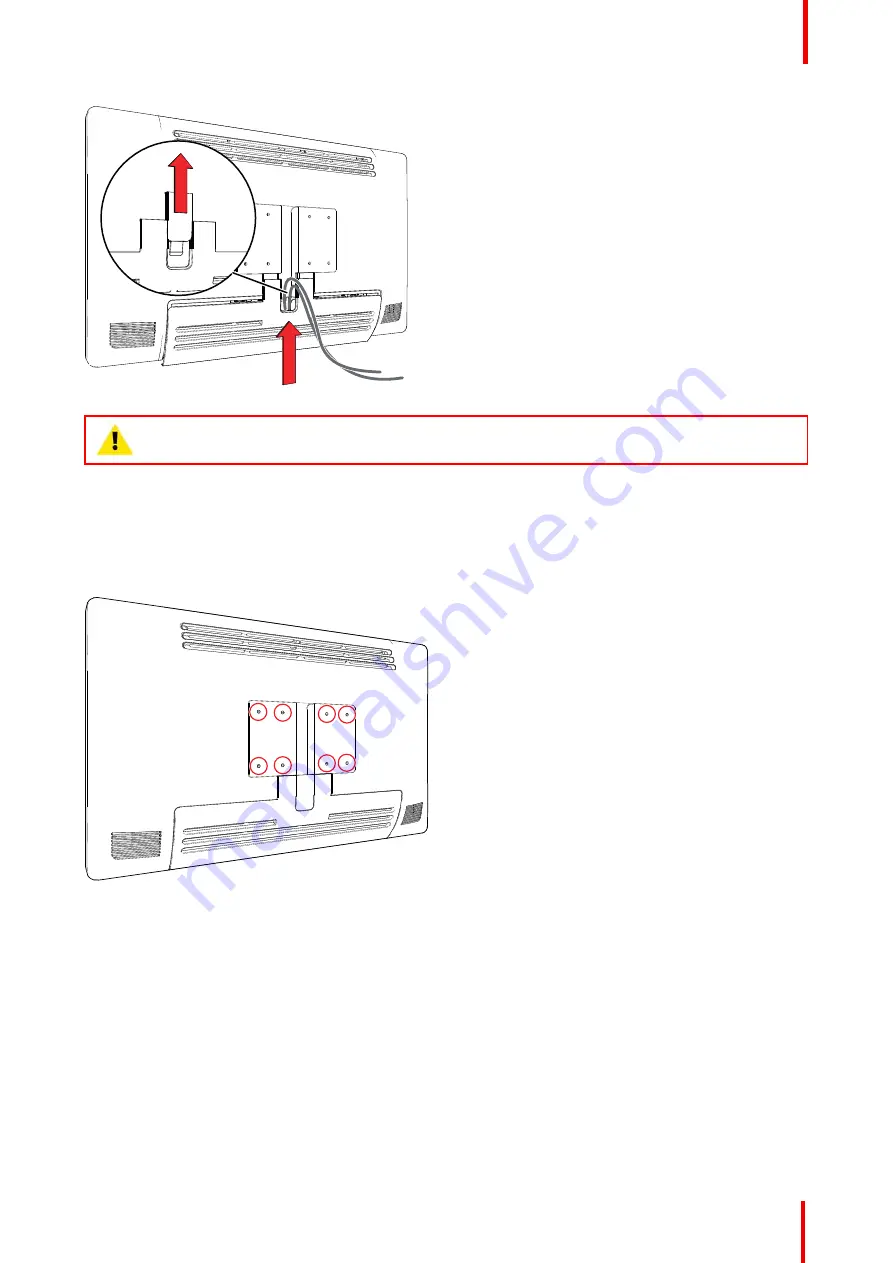
3.5 VESA mount installation

To install the display on a VESA mounting solution

The display can be attached to a VESA 100 mm or VESA 200 mm arm or stand.

Image 3-8

The VESA mounting holes at the back of the display are provided with M4-type blind fasteners to fix the VESA
mounting plate. Depending on the VESA plate thickness (T) and the thickness of possible washers (W), a
different screw length (L) should be selected.

Please respect the following rule to select an appropriate screw length:

L

min

= T + W + 15 mm

L

max

= T + W + 18 mm

Installation

Summary of Contents for MDSC-8231

Page 1: ...ENABLING BRIGHT OUTCOMES MDSC 8231 12G User Guide 31 UHD 4K surgical display MDSC 8231 ...

Page 2: ...Registered office Barco NV President Kennedypark 35 8500 Kortrijk Belgium www barco com en support www barco com Barco NV Beneluxpark 21 8500 Kortrijk Belgium www barco com en support www barco com ...

Page 3: ...2 4 6 DisplayPort connector 15 2 4 7 HDMI connector 16 2 4 8 DC out connector 16 3 Installation 17 3 1 Cover removal 18 3 2 Interface connection 18 3 3 Power supply connection 19 3 4 Cable routing 20 3 5 VESA mount installation 21 4 Daily operation 23 4 1 On Off switching 24 4 2 Keyboard locking unlocking 24 4 3 Power status LED 25 4 4 OSD menu activation 25 4 5 OSD menu navigation 25 4 6 Shortkey...

Page 4: ...and Picture input 37 5 3 8 Picture in Picture input 38 5 3 9 Picture in Picture mode 38 5 3 10 Picture in Picture position 38 5 3 11 Picture in Picture transparency 39 5 4 Configuration menu 39 5 4 1 Information 39 5 4 2 Language 39 5 4 3 OSD Time out 39 5 4 4 Recall Profile 40 5 4 5 Save Profile 40 5 5 System menu 40 5 5 1 Power on DVI 40 5 5 2 Power on DisplayPort 41 5 5 3 Control lock 41 5 5 4 ...

Page 5: ...R5911692 01 MDSC 8231 5 7 8 Legal disclaimer 59 7 9 Technical specifications 60 ...

Page 6: ...R5911692 01 MDSC 8231 6 ...

Page 7: ...7 R5911692 01 MDSC 8231 Welcome 1 ...

Page 8: ... that hides the cables for a clutter free set up Equipped with VESA 100 and VESA 200 interface to allow easy mounting on surgical booms and spring arms Available in different models this surgical display also features a host of connectivity options and remote control Ease of use Barco s MDSC 8231 allows easy cleaning thanks to its smooth surface and protective screen cover Features 31 inch wide sc...

Page 9: ...purchased some of the features and options described in this document may not apply to the display in user s hands Warnings cautions notes and tips There are four levels of precautionary or advisory statements that may be used in this user guide In descending order of importance they are WARNING Describes hazards or dangers that might result in personal injury or death CAUTION Describes hazards th...

Page 10: ...R5911692 01 MDSC 8231 10 Welcome ...

Page 11: ...11 R5911692 01 MDSC 8231 Parts controls and connectors 2 ...

Page 12: ...ortkey 2 Down key 3 Up key 4 OSD menu Enter key 5 Left Brightness decrease key 6 Right Brightness increase key 7 Stand by key Power mode LED 8 Keyboard lock unlock button membrane switch at the bottom of the display The keyboard lock unlock button may be activated accidentally when placing the display on a flat surface with the bottom facing downwards Persistent key pressures will automatically be...

Page 13: ...e link out or Quad link in top right 3 SDI 3 Single link in or Quad link in bottom right 4 SDI 4 Single link out or Quad link in bottom left 5 HDMI 2 in 6 HDMI 1 in 7 5 VDC 2 A power out 8 USB 2 0 type A interface 9 USB 2 0 type B interface 10 Main Right DisplayPort in 11 DVI D in 12 DVI D out 13 Potential Equalization pin POAG 14 2nd Left DisplayPort in 15 24 VDC power in The BNC SDI connectors m...

Page 14: ...I connector DVI D Overview Image 2 5 1 D2_Rx T M D S 2 D2_Rx T M D S 3 GND data 2 shield 4 Not connected 5 Not connected 6 SCL for DDC 7 SDA for DDC 8 Not connected 9 D1_Rx T M D S 10 D1_Rx T M D S 11 GND data 1 shield 12 Not connected 13 Not connected 14 5V output 15 GND cable sense 16 Hot plug detect 17 D0_Rx T M D S 18 D0_Rx T M D S 19 GND data 0 shield 20 Not connected 21 Not connected 22 GND ...

Page 15: ...Data 4 GND 2 4 5 Micro USB connector Overview 1 2 3 4 5 Image 2 8 1 5 VDC 2 Data 3 Data 4 GND 5 Not connected 2 4 6 DisplayPort connector Overview sink side pin out 19 17 15 13 11 9 7 5 3 1 20 18 16 14 12 10 8 6 4 2 Image 2 9 1 ML_Lane 3 n 2 GND 3 ML_Lane 3 p 4 ML_Lane 2 n 5 GND 6 ML_Lane 2 p 7 ML_Lane 1 n 8 GND 9 ML_Lane 1 p 10 ML_Lane 0 n Parts controls and connectors ...

Page 16: ...13 15 17 19 Image 2 10 1 T M D S Data2 2 T M D S Data2 Shield 3 T M D S Data2 4 T M D S Data1 5 T M D S Data1 Shield 6 T M D S Data1 7 T M D S Data0 8 T M D S Data0 Shield 9 T M D S Data0 10 T M D S Clock 11 T M D S Clock Shield 12 T M D S Clock 13 CEC 14 Not connected 15 DDC_SCL 16 DDC_SDA 17 DDC CEC GND 18 5VDC POWER 19 HDP 2 4 8 DC out connector Overview 1 2 Image 2 11 1 5 VDC 2 GND Parts contr...

Page 17: ...17 R5911692 01 MDSC 8231 Installation 3 ...

Page 18: ...MDSC 8231 to another display projector video recorder This chapter describes how to connect the different video interface types to the MDSC 8231 To connect the interfaces 1 Connect one or more video source s to the corresponding video inputs of the display For a list of supported video inputs see Technical specifications page 60 See SDI config page 35 about the possible SDI configuration modes 2 S...

Page 19: ...o available on a new DDC protocol on DVI and DisplayPort1 auxiliary channel 3 3 Power supply connection To connect the power supply 1 Connect the supplied external DC power supply unit to the 24 VDC power input of your display 2 Plug the other end of the external DC power supply into a grounded power outlet by means of the proper power cord delivered in the packaging Image 3 3 CAUTION To avoid ris...

Page 20: ...t the potential equalization pin POAG to the potential equalization terminal of the equipment Image 3 5 3 4 Cable routing To route the cables For displays to be mounted on a VESA arm with internal cable routing provisions route all cables through the cable routing channel then reinstall the connector compartment without removing the expansion clip Image 3 6 For displays to be mounted on a VESA arm...

Page 21: ...he display can be attached to a VESA 100 mm or VESA 200 mm arm or stand Image 3 8 The VESA mounting holes at the back of the display are provided with M4 type blind fasteners to fix the VESA mounting plate Depending on the VESA plate thickness T and the thickness of possible washers W a different screw length L should be selected Please respect the following rule to select an appropriate screw len...

Page 22: ...ON Use an arm that is in compliance with VESA requirements CAUTION The monitor VESA interface has been designed for a safety factor 6 to support 6 times the monitor weight In the medical system use an arm with suitable safety factor IEC60601 1 Installation ...

Page 23: ...23 R5911692 01 MDSC 8231 Daily operation 4 ...

Page 24: ...echanism has been implemented This means that the keyboard needs to be unlocked before it can be used to change any of the display settings By default all keys except the key will be dimmed to indicate that the keyboard is locked After unlocking the keyboard all keys will light up Touching any of these keys while the backlight is on will execute the function of the key However if no further action...

Page 25: ...the key As a result the OSD main menu comes up in the bottom right corner of the screen If no further actions are taken within the following 30 seconds the OSD menu will disappear again If after pressing the key the OSD lock window appears then this means that the OSD lock has been enabled Refer to Control lock OSD menu locking unlocking page 27 for more information and instructions to unlock the ...

Page 26: ...onfirm Press again or key to select other Menu items or exit from the Menu page by pressing the key 4 6 Shortkey functions 4 6 1 Main source selection To quickly select the main source 1 Unlock the keyboard see Keyboard locking unlocking page 24 2 Press the key to scroll through all the possible input signals and quickly select the main source Available main source options may differ depending on ...

Page 27: ...the key after unlocking the keyboard will not activate the OSD menu but will make the OSD lock window appear The OSD menu can only be accessed after pressing a sequence of keys OSD lock Sequence 5 6 6 3 Image 4 5 To lock unlock the menu 1 Unlock the keyboard see Keyboard locking unlocking page 24 2 Press the key 3 When the OSD lock window appears press the following key sequence to unlock the OSD ...

Page 28: ...R5911692 01 MDSC 8231 28 Daily operation ...

Page 29: ...Not all features described in the chapter Advanced operation are available The features not available in specific software versions are grayed out in the OSD menu R5911692 01 MDSC 8231 Advanced operation 5 ...

Page 30: ...tive respectively User 1 User 2 User 3 To select a profile 1 Bring up the OSD main menu 2 Navigate to the Picture menu 3 Enter the Profile submenu 4 Select one of the available profiles and confirm 5 1 2 Brightness To adjust the brightness level 1 Bring up the OSD main menu 2 Navigate to the Picture menu 3 Enter the Brightness submenu The command bar Brightness is highlighted 4 Set the brightness ...

Page 31: ...ion commands to adjust the gain and offset of red green and blue primary colors To select a color temperature preset 1 Bring up the OSD main menu 2 Navigate to the Picture menu 3 Enter the Color Temperature submenu 4 Select one of the available color temperature presets and confirm If you selected the User color temperature preset a new menu will be displayed allowing you to manually adjust the ga...

Page 32: ...mmand allows to smoothen or sharpen the image Following values apply 12 Smoothen image 12 Neutral image default 12 Sharpen image To adjust the sharpness level 1 Bring up the OSD main menu 2 Navigate to the Picture menu 3 Enter the Sharpness submenu The command bar Sharpness is highlighted 4 Set the sharpness level as desired and confirm Sharpness control is not available when DisplayPort mode DP 1...

Page 33: ...ge according to the input signal range The available input ranges are 0 255 16 235 16 255 To select the input range 1 Bring up the OSD main menu 2 Navigate to the Picture Advanced menu 3 Enter the Input range submenu 4 Select one of the available input ranges and confirm Input range control is available only when the selected main source see Main Source page 34 is DVI or SDI 5 2 4 Image Size About...

Page 34: ... function allows you to adjust the image resolution of the preferred timing detailed in the EDID exposed to the DP input The available options are 4K 17 9 for image resolution of 4096 x 2160 UHD 16 9 for image resolution of 3840 x 2160 Image resolution of the preferred timing detailed in the EDID exposed to HDMI 1 and HDMI 2 are predefined as follows HDMI 1 16 9 HDMI 2 17 9 To enable disable horiz...

Page 35: ... Input Select menu 3 Enter the DP mode submenu 4 Select one of the available DisplayPort modes and confirm 5 3 3 4K SDI mode About 4K SDI mode The available 4K SDI modes for your display are Square division SQD 2 sample interleave 2SI Auto Select Auto only when the SDI mode is present in the SDI video stream To select the 4K SDI mode 1 Bring up the OSD main menu 2 Navigate to the Input Select menu...

Page 36: ...play depend on the selected SDI configuration mode See the following table for more details Main source Backup source DP HDMI SDI 1 None DVI SDI 3 1 DP HDMI SDI 1 SDI 3 2 None DVI DP HDMI QUAD LINK 3G SDI 3 None DVI The failover input can only be selected when both 1 the Auto search function is disabled see Auto search page 36 and 2 the PiP PaP Modes function is disabled see Picture and Picture in...

Page 37: ...le Picture and Picture combinations between the Primary input main source and the Secondary input PaP image is displayed in the following table Primary input Secondary input DP 1 1 HDMI 2 0 1 HDMI 2 0 2 DVI SDI 3 HDMI 2 0 1 HDMI 2 0 2 DP 1 1 DVI SDI 3 DVI SDI 3 DP 1 1 HDMI 2 0 1 HDMI 2 0 2 Both primary and secondary input are limited to FHD resolution max The Video Parameters applied to the Primar...

Page 38: ...Input Select menu 3 Enter the PiP Input submenu 4 Select one of the available PiP inputs or NONE and confirm 5 3 9 Picture in Picture mode About Picture in Picture mode The available Picture in Picture modes for your display are Large PiP 35 of display horizontal size in top or bottom of right corners Small PiP 25 of display horizontal size in top or bottom of right corners To select Picture in Pi...

Page 39: ...release hardware and firmware identification Keyboard release hardware and firmware identification SDI module release hardware and firmware identification Serial Number unit serial number Main FPGA release firmware identification To access information 1 Bring up the OSD main menu 2 Navigate to the Configuration menu 3 Enter the Information submenu 5 4 2 Language About languages The OSD menu of you...

Page 40: ...submenu 4 Select one of the available profiles to recall and confirm 5 4 5 Save Profile About saving profiles The user can modify the default video parameters associated to each profile and save the new parameter settings under the User 1 User 2 or User 3 profile The Factory and X Ray profiles can be modified but the factory default can t be overwritten and can always be recalled through the recal...

Page 41: ...yboard can only be accessed after pressing a sequence of keys Refer to Control lock OSD menu locking unlocking page 27 To enable disable control locking 1 Bring up the OSD main menu 2 Navigate to the System menu 3 Enter the Control Lock submenu 4 Enable Disable Control locking as desired and confirm 5 5 4 Power saving About power saving When the selected input s is are missing main 2nd and failove...

Page 42: ...rt of the image will be down scaled to FHD resolution To enable disable DVI output 1 Bring up the OSD main menu 2 Navigate to the System menu 3 Enter the DVI output submenu 4 Enable Disable DVI output as desired and confirm 5 5 6 Operating hours About operating hours This information shows the operation hours of your display To consult operating hours 1 Bring up the OSD main menu 2 Navigate to the...

Page 43: ...43 R5911692 01 MDSC 8231 Troubleshooting 6 ...

Page 44: ...isplay Flashing images Serial connection not available After reboot the serial connection on the USB type B port is not present COM port not visible Reboot the display OSD disappears during input signal switching OSD disappears during input signal switching maximum 2 seconds No action required This is normal behavior Half of the screen corrupt After switching from a profile with HDMI UHD 4 2 0 inp...

Page 45: ...45 R5911692 01 MDSC 8231 Important information 7 ...

Page 46: ... obstruct the air flow and cause temperature increase of the electronics General recommendations Keep the monitor clean to prolong its operational lifetime LCD panel performance may deteriorate in the long term Periodically check that it is correctly operating Periodically check the tightness of the VESA mount screws If not sufficiently tight the monitor may detach from the arm which may result in...

Page 47: ...nnection to peripheral devices Power cords Europe H05VV F or H05VVH2 F PVC cord with appropriate EU plug US and Canada hospital grade cord set has to be used provided with instructions to indicate that grounding reliability can be achieved only when the equipment is connected to an equivalent receptacle marked hospital only or hospital grade These instructions need to be marked either on the equip...

Page 48: ...njury caused by mishandling or improper installation Malfunctions Disconnect the equipment s power cord from the AC inlet and refer servicing to qualified service technicians under the following conditions If the power cord or plug is damaged or frayed If liquid has been spilled into the equipment If the equipment has been exposed to rain or water If the equipment does not operate normally when th...

Page 49: ...y RoHS compliance Türkiye Cumhuriyeti AEEE Yönetmeliğine Uygundur Republic of Turkey In conformity with the WEEE Regulation 中国大陆 RoHS Chinese Mainland RoHS 根据中国大陆 电器电子产品有害物质限制使用管理办法 也称为中国大陆RoHS 以下部分列出了 Barco产品中可能包含的有毒和 或有害物质的名称和含量 中国大陆RoHS指令包含在中国信息产业部MCV标 准 电子信息产品中有毒物质的限量要求 中 According to the Management Methods for the Restriction of the Use of Hazardous Substances in Electrical and Electronic Pro...

Page 50: ...mation Products EIP that are sold within Chinese Mainland must comply with the Marking for the restriction of the use of hazardous substances in electrical and electronic product of Chinese Mainland marked with the Environmental Friendly Use Period EFUP logo The number inside the EFUP logo that Barco uses please refer to the photo is based on the General guidelines of environment friendly use peri...

Page 51: ... label and or whenever such declaration is missing can be rejected by Seller or by the Authorized Service Provider and shipped back at Customer expenses 7 4 Cleaning and disinfection Instructions Be sure to unplug the power cord from the mains when cleaning your LCD monitor Take care not to scratch the front surface with any hard or abrasive material Dust finger marks grease etc can be removed wit...

Page 52: ...rovide reasonable protection against harmful interference in a residential installation This device generates uses and can radiate radio frequency energy and if not installed and used in accordance with the instructions may cause harmful interference to radio communications However there is no guarantee that interference will not occur in a particular installation If this device does cause harmful...

Page 53: ...rient or relocate the receiving antenna or equipment Increase the separation between the equipment and receiver Connect the equipment into an outlet on a circuit different from that to which the receiver is connected Consult the dealer or an experienced technician for help Electromagnetic immunity The MDSC 8231 is intended for use in the electromagnetic environment IEC 60601 1 2 4th edition specif...

Page 54: ...or 25 cycles 5 UT 95 dip in UT for 5 seconds continued operation during power mains interruptions it is recommended that the MDSC 8231 be powered from an uninterruptible power supply or a battery Power frequency 50 60 Hz magnetic field IEC 61000 4 8 30 A m 30 A m Power frequency magnetic fields should be at levels characteristic of a typical location in a typical commercial or hospital environment...

Page 55: ... of equipment marked with symbol At 80 MHz and 800 MHz the higher frequency range applies These guidelines may not apply in all situations Electromagnetic propagation is affected by absorption and reflection from structures objects and people Recommended separation distance The MDSC 8231 is intended for use in an electromagnetic environment in which radiated RF disturbances are controlled The cust...

Page 56: ...following symbols nonrestrictive list Indicates the device meets the requirements of the applicable EC directives regulations Indicates compliance with Part 15 of the FCC rules Class A or Class B E346057 Indicates the device is approved according to the UL Recognition regulations E346057 MEDICAL GENERAL MEDICAL EQUIPMENT AS TO ELECTRICAL SHOCK FIRE AND MECHANICAL HAZARDS ONLY IN ACCORDANCE WITH AN...

Page 57: ...ed Stated of America restricts this device to sale by or on the order of a licensed healthcare practitioner IS 13252 Part 1 IEC 60950 1 R xxxxxxxx www bis gov in Indicates the device is approved according to the BIS regulations Indicates the device is approved according to the INMETRO regulations Indicates the USB connectors on the device Indicates the DisplayPort connectors on the device Indicate...

Page 58: ...or Consult the Instruction For Use on website address that is provided as eIFU indicator Indicates this device must not be thrown in the trash but must be recycled according to the European WEEE Waste Electrical and Electronic Equipment directive Indicates Direct Current DC Indicates Alternating Current AC Stand by Equipotentiality or Protective earth ground Symbols on the box On the box of the de...

Page 59: ...al disclaimer Disclaimer notice Although every attempt has been made to achieve technical accuracy in this document we assume no responsibility for errors that may be found Our goal is to provide you with the most accurate and usable documentation possible if you discover errors please let us know Barco software products are the property of Barco They are distributed under copyright by Barco NV or...

Page 60: ...e glass Keyboard Capacitive touch keyboard Video input signals 4K UHD input 1x DP 1 1 up to 4096 x 2160 30Hz 2x DP 1 1 up to 2048 x 2160 50Hz 60Hz 1x DP 1 2 MST up to 4096 x 2160 50Hz 60Hz 2x HDMI 2 0 up to 4096 x 2160 50Hz 60Hz 7 4K SDI 4x 3G SDI Quad link each link up to 2048 x 1080 50 60 Hz 2x 12G SDI up to 4096 x 2160 50 60 Hz SDI 1 or SDI 3 FHD input upscaled to 4K 1x DVI 1x 3G SDI SDI 1 or S...

Page 61: ...Safety and Essential Performance includes Deviations for United States CAN CSA C22 2 No 60601 1 2014 Medical Electrical Equipment Part 1 General Requirements for Basic Safety and Essential Performance includes National Differences for Canada IEC 60601 1 2005 Third Edition CORR 1 2006 CORR 2 2007 A1 2012 General requirements for basic safety and essential performance EN 60601 1 2006 CORR 2010 A1 20...

Page 62: ...0p 60 00Hz Y Y Y Y 1280x1024p 60 013Hz N Y Y Y 1280x1024p 75 025Hz N Y N Y 1280x1024p 85 00Hz N Y N Y 1400x1050p 60 00Hz N Y N Y 1600x1200p 60 00Hz N Y Y Y 1680x1050p 59 95Hz N Y N Y 1920X1080i 50Hz Y Y Y Y 1920X1080i 59 94Hz Y Y Y Y 1920X1080i 60Hz Y Y Y Y 1920x1080p 25Hz Y Y Y Y 1920x1080p 29 97Hz Y Y Y Y 1920x1080p 30 00Hz Y Y Y Y 1920x1080p 50 00Hz Y Y Y Y 1920x1080p 59 94Hz Y Y Y Y 1920x1080p...

Page 63: ...0 00Hz Y Y Y Y N N 3840x2160 50 00Hz Y N Y Y Y Y 3840x2160 60 00Hz Y N Y Y Y Y 4096x2160 25 00Hz Y Y Y Y N N 4096x2160 30 00Hz Y Y Y Y N N 4096x2160 50 00Hz Y N Y Y Y Y 4096x2160 60 00Hz Y N Y Y Y Y Accepted formats Square division 2 sample interleave Dimensions 777 701 200 288 5 100 100 186 371 2 472 472 92 Image 7 1 Important information ...

Page 64: ... NV Beneluxpark 21 8500 Kortrijk Belgium Registered office Barco NV President Kennedypark 35 8500 Kortrijk Belgium www barco com R5911692 01 2020 03 09 Barco NV President Kennedypark 35 8500 Kortrijk Belgium ...

Reviews: