8. Advanced System Tuning With The System Tuning Extension
3. In the Measurement tab select the Loudspeaker Setup representing the speaker setup that is supposed to be tuned, for example
3D ls
fi
le
-
Understand and click
Yes
in the warning dialog
-
In
Group Name
check all groups that should be measured and tuned, i.e. check Ring, Ceiling, Subwoofer
-
In
Measure Microphone Position
select the number of microphone positions that are going to be used in the measurement,
i.e. 1 to 8
-
Set a
Start Delay
for example
20s
Note:
The number of Measure Microphone Positions may exceed the number of microphones actually being connected to
the system. In that case, the set of position will be measured in multiple cycles. The Start Delay setting describes the
amount of time that will pass between pressing the Start button to begin the measurement and the
fi
rst playback of
the measurement sweep. This is meant as a health safety feature by allowing the user to leave the room or place ear
protectors before starting the measurement sweeps.
4. Go to
Settings
tab
-
In
Preferences
tab set the
Number of Simultaneous Microphone Inputs
to the number of connected microphones to the
system, i.e. 4
-
Keep all other default values
5. Go to
Input Routing
-
Create a routing for all available microphones to the
Soundcard Inputs
6. Go to Output Routing
-
Create a diagonal line from cell 1/1 in the
fi
rst loudspeaker group Ring to cell 3/47 in the last loudspeaker group Subwoofer
Note:
In the matrix, the rows represent the loudspeakers of your loudspeaker setup that are assigned to render slots, each with
an individual color. The columns represent physical audio outputs of the processor, which can be accessed at the rear
of your IOSONO CORE hardware. You may con
fi
gure your individual output routing here. In our example,
- Speakers 1-15 in render slot 1 are connected to outputs 1-15 (dummy speakers 16 and 17 require no connection to
physical audio outputs)
- Speakers 1-4 in render slot 2 are connected to outputs 18-21
- Speakers 1-2 in render slot 3 are connected to outputs 22-23 and speakers 1-5 in render slot 4 are connected to outputs
24-28
Therefore we want to use the automatically con
fi
gured diagonal 1-to-1 routing.
7. Go to the MADI 1 tab
-
Set
Synchronization
to
Signal
-
In
Input Select
select
Optical
Note:
Depending on the I/O con
fi
guration of the IOSONO CORE processor there will be setting tabs for each soundcard dis-
played. In this example with IOSONO CORE I/O Con
fi
g M (1x MADI) only MADI 1 is displayed. In this example the
microphone preamp is the sync source and the IOSONO CORE is the sync slave connected via MADI optical. In case
of correct settings the Status lights SYNC 48kHz MADI should all turn green.
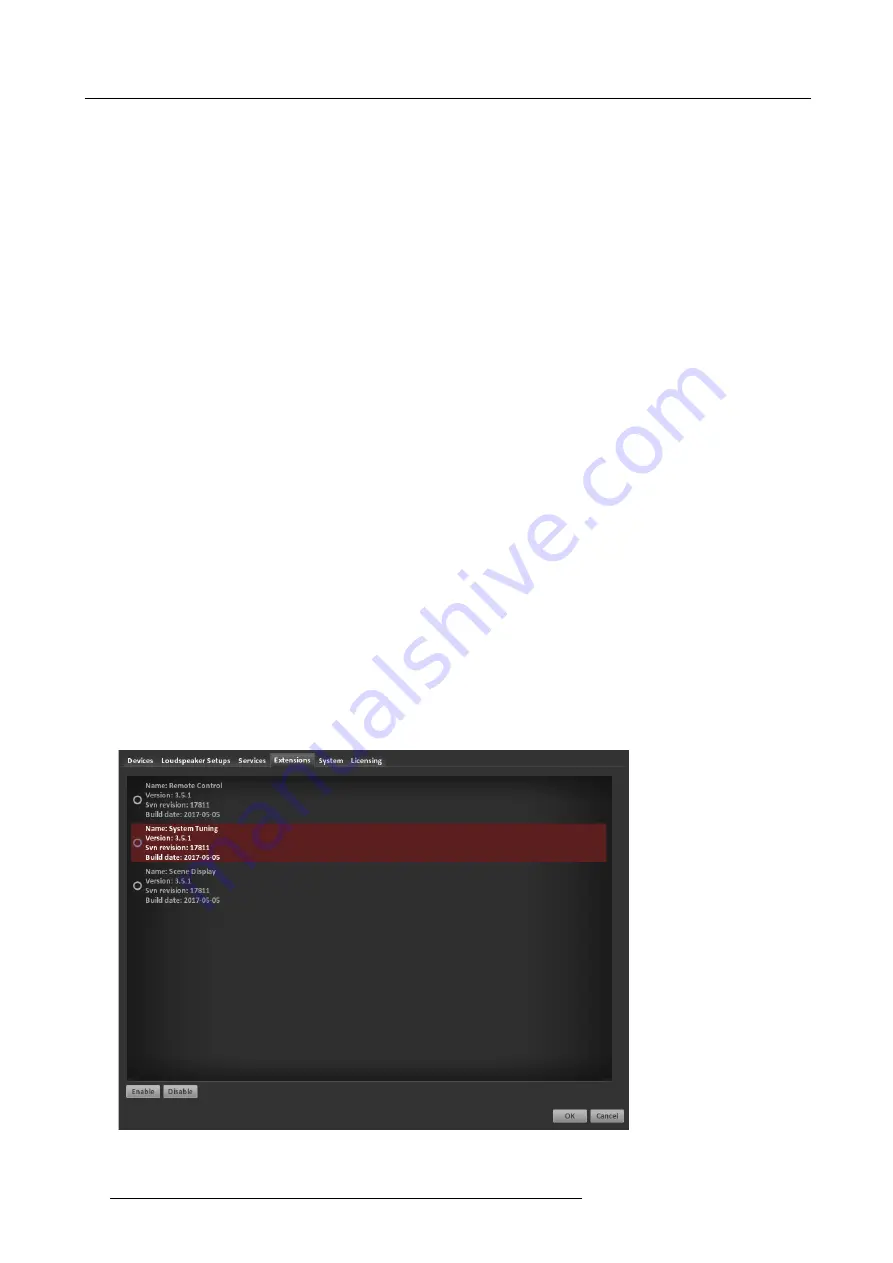
Image 8-2
Extensions overview
50
R5906746 IOSONO CORE 08/05/2017
Summary of Contents for Iosono Core R9801500
Page 4: ......
Page 6: ...1 Introduction 2 R5906746 IOSONO CORE 08 05 2017 ...
Page 14: ...4 System Startup 10 R5906746 IOSONO CORE 08 05 2017 ...
Page 24: ...5 Initial System Configuration 20 R5906746 IOSONO CORE 08 05 2017 ...
Page 52: ...7 Step By Step Configuration 48 R5906746 IOSONO CORE 08 05 2017 ...
Page 60: ...8 Advanced System Tuning With The System Tuning Extension 56 R5906746 IOSONO CORE 08 05 2017 ...


