background image

Operation

62

User manual CCFD 2320

filters to filter possible high-frequent distortion from an 

analog

 video signal.

Select a different filter in case the image contains high-
frequent noise or distortion. Select the filter that gives 
the best result.

Readjustment of sample phase is necessary after 
selection of a different filter.

Advanced functions in the Settings menu

Display Function

See the Glossary section for more information about 
display functions.

The display contains a number of factory-defined and 
user-defined lookup tables (LUTs) to define the display 
(transfer) function.
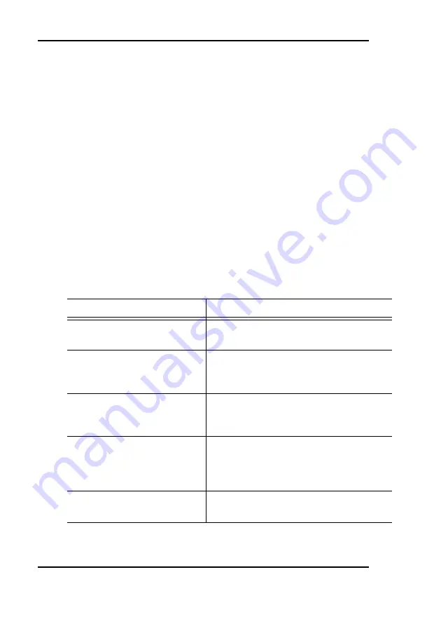
Name

Description

sRGB

Select the sRGB standard display 
function

Gamma 2.2

Select this display function in case 
the display is to replace a CRT dis-
play with a gamma of 2.2

Gamma 1.8

Select this display function in case 
the display is to replace a CRT dis-
play with a gamma of 1.8

User

This is a user-programmable display 
function (dedicated software needed 
to define the associated lookup 
table)

Native

If you select Native, a linear LUT will 
be selected

Summary of Contents for CCFD 2320

Page 1: ...Installation User Manual User manual CCFD 2320...

Page 2: ...ew LLC 3059 Premiere Parkway Duluth Georgia 30097 USA Phone 1 678 475 8000 Fax 1 678 475 8100 E mail medical us barco com Barco LTD 17th floor Kuohwa Building 868 6 Chungcheng Rd Chungho City Taipei C...

Page 3: ...rate and usable documentation possible if you discover errors please let us know BarcoView software products are the property of BarcoView They are distributed under copyright by Barco N V or BarcoVie...

Page 4: ...may cause harmful interference to radio communications Operation of this equipment in a residential area is likely to cause harmful interference in which case the user will be required to correct the...

Page 5: ...lay installation 17 After unpacking the display 17 Power connection 20 Video connection 22 USB connection 25 RS 232 connection 26 Cable routing 27 Software installation 28 Contrast enhancer installati...

Page 6: ...display operation 60 Introduction 60 Advanced functions in the Adjustments menu 61 Advanced functions in the Settings menu 62 Advanced functions in the Presets menu 66 Advanced functions in the Gener...

Page 7: ...to all warnings on the apparatus and in the operating instructions manual Follow all instructions for operation and use Electrical shock Power connection Power requirements The apparatus must be power...

Page 8: ...ar attention to cords at plugs and receptacles Water and moisture Never expose the apparatus to rain or moisture Never use the apparatus near water e g near a bathtub washbasin swimming pool kitchen s...

Page 9: ...e following symbols Symbols used throughout the manual Indicates the display is approved according to the CE regulations Indicates the display is approved according to the UL regulations Indicates the...

Page 10: ...ns and environments Color I Guard Color I GUARD is Barco s patent pending built in calibration device continuously maintaining image quality Together with the ColorisTalk software tool the Color I Gua...

Page 11: ...lows to use the display for viewing portrait or landscape image resolutions The user can easily change the panel height and viewing angle allowing to use the display in the optimal viewing conditions...

Page 12: ...d documentation This manual If some of the items are missing please contact the reseller from whom you have purchased the unit Parts controls and connectors Front Figure 1 1 Ambient Light ALC sensor W...

Page 13: ...when the display is on when enabled in the on screen menus The LED is orange when the display is in Stand by power saving mode 3 Control wheel The control wheel can be pushed like a push button and t...

Page 14: ...e display is shipped to the customer 3 Tilt swivel foot 4 Tilt swivel foot strap The display is shipped with this strap in the foot to protect the tilt swivel mechanism during transport After unpackin...

Page 15: ...mera to this connector 7 USB upstream port USB 1 1 standard is supported Connect this connector to the PC USB bus if you wish to control the display via the USB bus or if you simply wish to connect US...

Page 16: ...Overview 16 User manual CCFD 2320 10 RS 232 input D Sub 9 female Connect this connector to a PC COM port if you wish to control the display via RS 232...

Page 17: ...g and stable table or desk Keep the display away from heat sources and provide enough ventilation around the display Do not scratch or apply pressure to the LCD panel This may damage the panel permane...

Page 18: ...later Adjust the panel orientation You can change the orientation of the panel at any time but it is more convenient to select landscape or portrait orientation before connecting the cables The displ...

Page 19: ...the orientation Should you change the panel orientation without tilting it first you might irreversibly damage the tilt swivel mechanism Figure 5 3 To change from portrait to landscape turn the panel...

Page 20: ...panel orientation If you use the display stand alone the image orientation will not change with the panel orientation Only the orientation of the on screen display OSD will change automatically in ca...

Page 21: ...cable to the AC input of the 12V DC power supply Figure 8 4 Connect the other end of the power cord to a grounded power outlet We recommend to use an additional surge protector between the power suppl...

Page 22: ...or more of these inputs If several video inputs are connected meaning the display is connected to different video controller boards you can switch inputs by using the display s on screen display Conn...

Page 23: ...isplay 2 Connect the other end of the DVI cable to the DVI connector of the display controller If this board has 2 video heads 2 video outputs connect to Head A Connecting DVI signals Two displays 1 C...

Page 24: ...able is not delivered with the system Proceed as follows 1 Connect one end of the signal cable to the analog video output monochrome of the PC 2 Connect the Video signal to the display s BNC input lab...

Page 25: ...r through the USB bus Moreover the USB connection allows you to use the display as USB hub to which you can connect USB devices such as a keyboard mouse or digital camera To connect the USB cable 1 Co...

Page 26: ...e you can use USB connection To connect the RS 232 cable 1 Connect one end of the RS 232 cable to a PC COM port 2 Connect the other end of the RS 232 cable to the display s RS232 IN connector 3 If the...

Page 27: ...are positioned under the bulge in the cover Push the cables into the clipses on the rear of the tilt swivel foot Bind the cables together above and under the foot by means of the 2 velcro strips atta...

Page 28: ...software 1 Insert your ColorisTalk software CD into your computer s CD drive 2 If the Installation Wizard doesn t start within one minute browse the contents of the CD and double click on the file Set...

Page 29: ...position Carefully place the top of the contrast enhancer at the inside of the top edge of the display bezel see figure Figure 16 1 Contrast enhancer 2 Edge of display bezel 3 Rear flaps 3 Now swing...

Page 30: ...window represent the displays connected to the computer Each display must be connected through USB The order in which the icons appear represents the logical order of the displays E g if two displays...

Page 31: ...nsation Tab pages The tab pages contain the information you can view and the functions you can perform The number of tabs and the contents of the tab pages depend on the button you have selected Overv...

Page 32: ...n calibrated mode when Ambient Light Compensation is enabled when Ambient Light Compensation is disabled but the color temperature or white luminance do not match the values in the Settings dialogs Th...

Page 33: ...is xxxxx where xxxxx is the display serial number Color temperature Gamma and White luminance can be selected with the Settings functions Video information To view video information 1 In the top of th...

Page 34: ...displays each time it starts up each time you click the Configure Now button in the Overview Status tab Version information To view version information 1 In the top of the window click the icon repres...

Page 35: ...site Registration information To view registration information 1 Click the Overview button 2 In the Product Info tab page you can see the registration information The registration information lists t...

Page 36: ...will be expressed in the program Candela per square meter or foot Lambert Settings functions Color temperatures To select a color temperature 1 Click the Settings button 2 In the Main tab page you can...

Page 37: ...be reached with the given settings of x y The color temperature however will match the given x y co ordinates Gamma functions To select a gamma function 1 Click the Settings button 2 In the Main tab...

Page 38: ...n ALC on off 1 Click the Settings button 2 In the Main tab page click the Advanced button The Advanced dialog box appears 3 To switch ALC on check the Enable Ambient Light Compensation check box Impor...

Page 39: ...When the display is on and no on screen display is visible push the control wheel at the front for a few seconds to switch the display in stand by The LED turns orange Figure 17 When the display is i...

Page 40: ...om the main menu Others are grouped in sub menus The content of the on screen menus depends on the selected video input The following functions are present in analog mode but are not present in digita...

Page 41: ...ou exit the menu system 4 To change an adjustment value turn the control wheel to select the adjustment and click the wheel shortly The adjustment name appears as well as the current adjustment value...

Page 42: ...the Autoset function should meet the following requirements The edges of the image should have an intensity of at least 15 video amplitude E g a Windows desktop pattern would be a good image provided...

Page 43: ...cessary if you have connected and selected digital DVI video To perform geometry adjustments 1 Turn the control wheel to display the on screen display The Main Menu appears 2 Turn the control wheel to...

Page 44: ...the control wheel to position the image horizontally inside the active video window Vert Pos Turn the control wheel to position the image vertically inside the active video window Scaling Click to sel...

Page 45: ...j 5 Click the control wheel to execute the function 6 Turn the control wheel to change the Video Contrast value 7 Click the control wheel to confirm the change of the value and return to the Video Con...

Page 46: ...k the control wheel to enter the Video Brightness menu 4 Turn the control wheel to select Man Brightness adj 5 Click the control wheel to execute the function 6 Turn the control wheel to change the Vi...

Page 47: ...lick the control wheel to enter the Color Temp selection menu 6 Turn the control wheel to select a color temperature You can select the following color temperatures D50 D55 D65 D93 User and Native Whi...

Page 48: ...eel to select changing the color temperature in Kelvin units or x y co ordinates Confirm the selection by clicking the control wheel 9 When changing Kelvin units Turn the control wheel to change the v...

Page 49: ...display in stand by mode To disable user controls 1 Turn the control wheel to display the on screen display The Main Menu appears 2 Turn the control wheel to select Settings 3 Click the control wheel...

Page 50: ...4 must be performed in maximum 3 seconds 5 Turn the control wheel to select Settings 6 Click the control wheel to enter the Settings menu 7 Turn the control wheel to select User Controls 8 Click the...

Page 51: ...st the target luminance to which the display will be stabi lized Yes Adjustments Perform Geometry and Phase adjustments Yes Input Selec tion Select which video signal will be displayed Digital DVI or...

Page 52: ...line pattern or characters Name Description Full Autoset Perform all Autoset functions below one after another Automatic Geometry Adjust the image geometry auto matically This function displays the co...

Page 53: ...amplitude Video Contrast This menu is not available in DVI mode Video Brightness This menu is not available in DVI mode Name Description Contrast CAL Pos Switch to calibrated position of contrast Man...

Page 54: ...Operation 54 User manual CCFD 2320 Luminance Name Description Target Value Manually adjust the luminance The luminance is indicated in cd m...

Page 55: ...active video win dow No Scaling Select the desired scaling option None The image is not scaled Best Fit The image is scaled proportionally to obtain the best fit Full Screen The image is scaled non p...

Page 56: ...e This is the same function as in the Autoset menu Frequency Adjust the video sampling fre quency manually However we recommend you use the Automatic Phase function Autoset menu Man Phase adj Adjust t...

Page 57: ...l be switched off BNC Select the BNC input Conse quently the Automatic setting will be switched off The BNC input is for monochrome video only Name Description DPMS Switch on off the automatic power s...

Page 58: ...some time Name Description Re name Change the name of the program mable Preset in the programmable memory location only Turn the control wheel to change the cur rent character Click the wheel to move...

Page 59: ...al time the display has been operating including the time in stand by Backlight Lifetime Indicates the total time the display has been operating excluding the time in stand by Name Description Input S...

Page 60: ...nctions About the Advanced functions The advanced functions are extensions of the OSD menus A standard user browsing through the OSD system sees only the standard functions When logged in in advanced...

Page 61: ...ible level you are likely to work in Next execute this function Min Luminance Adjust this value until the luminance is at the level you wish to work with when the ambient light is at the minimum level...

Page 62: ...re information about display functions The display contains a number of factory defined and user defined lookup tables LUTs to define the display transfer function Name Description sRGB Select the sRG...

Page 63: ...rol wheel Turn the wheel to select Standard or Extended input mode Then click the wheel again to enter the selected submenu The following input mode settings can be selected Test This selection is mea...

Page 64: ...to the for mula 0 3R 0 59G 0 11B This single luminance signal drives the RGB sub pixels of the panel equally Use this setting in case the imag ing board is a color board and if the signal must be disp...

Page 65: ...lumi nance value according to the for mula 0 3G 0 59B 0 11R This single luminance signal drives the RGB sub pixels of the panel equally BRG Y The RGB video signals from the imaging board are calculate...

Page 66: ...in the Presets menu Clear user Presets Click the control wheel if you wish to reset all the settings of all user Presets In the menu that appears next click on Proceed to reset the settings RBG Y The...

Page 67: ...tes the display serial number Display Stock No Indicates the display order number Panel Indicates the flat panel serial num ber Panel Prod Date Indicates the flat panel production date Name Descriptio...

Page 68: ...Display Lifetime Indicates the total time the display has been operating including the time in stand by Backlight Lifetime Indicates the total time the display has been operating excluding the time i...

Page 69: ...ution of potassium salts obtained by leaching wood ashes It is much used in making soap etc Acid Detergents with fluoride Detergents with ammonia Detergents with abrasives Steel wool Sponge with abras...

Page 70: ...e nonabrasive cloth and lightly moisten the cloth with a solution of 25 Isopropyl Alcohol IPA and 75 de ionized or distilled water E g Cleareen a product of Certified Laboratories 3 Gently clean the p...

Page 71: ...ns Screen remains black Please check the installation procedure in this manual If the LED at the front is orange the display is in stand by Check in the Windows Display Properties if the display contr...

Page 72: ...read the paragraph about the User Controls function The image is non propor tionally spread out over the screen Select another resolution in the Windows Display Properties control panel Switch the Sc...

Page 73: ...l CCFD 2320 73 On a dual head system the images on the left and right display seem to be switched Switch the video cables at the display controller or at the display video inputs Problem description P...

Page 74: ...06 mm Viewing angle 10 1 contrast Vertical 170 Horizontal 170 Pixel Pitch 0 255 mm H x 0 255 mm V Native color resolution 8 bits sub pixel Luminance 130 cd m calibrated 180 cd m max in Native White co...

Page 75: ...60 75 85 Hz 1600 x 1200 59 60 Hz USB standard supported USB 1 1 Power source Input for 12 VDC power sup ply unit 90 264 VAC Input for display 12 VDC The supplied 12VDC power supply must be used Power...

Page 76: ...CCFD 2320 Connector pin assignments DVI connector Storage Temperature 20 C to 60 C Humidity 8 80 non condensing for operation 5 95 non condensing for storage Altitude 7500 m storage 3000 m operation...

Page 77: ...Pin no Signal 1 TMDS DATA 2 14 5V POWER 2 TMDS DATA 2 15 GND 3 GND 16 HOT PLUG DETECT 4 NC 17 TMDS DATA 0 5 NC 18 TMDS DATA 0 6 DDC CLOCK 19 GND 7 DDC DATA 20 NC 8 NC 21 NC 9 TMDS DATA 1 22 GND 10 TM...

Page 78: ...or temperature and white luminance can be defined in the display s OSD or in external software as ColorisTalk The display is calibrated continuously by means of the incorporated I Guard sensor It is a...

Page 79: ...igital data from the computer into digital or analog video voltages Most of the common imaging boards contain just one set of video and sync outputs However some high end boards like some of the Barco...

Page 80: ...isplay uses default settings to display the image When you make adjustments and save the changes the current Preset is saved as programmable Preset If this happens while all programmable Presets are o...

Page 81: ...untered including the model and serial number of the equipment in which the problem has arisen 1 2 The Customer Support person shall diagnose the problem experienced by the Customer and shall advise t...

Page 82: ...ntegrated by Customer or a third party into BarcoView supplied equipment 2 2 Any host configuration not explicitly supported by BarcoView 2 3 All software installed on the system whether they are acqu...

Page 83: ...s 3 2 Repairs to equipment under warranty resulting from improper maintenance or repair performed by the Customer or its officers agents employees or representatives shall be borne by the Customer at...

Page 84: ...allation operation or suitability for use of any products or services covered by or furnished under this warranty condition whether arising out of contract negligence strict tort warranty or otherwise...

Page 85: ...rror mechanical or electrical failure and should not be relied upon in inappropriate applications or without proper backup and or other safety precautions whenever personal injury or property damage m...

Page 86: ...Warranty Statement 86 User manual CCFD 2320 This page intentionally left blank...

Page 87: ...Warranty Statement User manual CCFD 2320 87...

Reviews: