Installation & Operating Instructions
“BAPI-Stat 3” Room Sensor
Building Automation Products, Inc., 750 North Royal Avenue, Gays Mills, WI 54631 USA
Tel:+1-608-735-4800 • Fax+1-608-735-4804 • E-mail:[email protected] • Web:www.bapihvac.com
rev. 01/30/14
24694_ins_BS3
5 of 6
ADJUSTMENT PROCEDURE FOR EACH DIP SWITCH IN S1:
°F OR °C DISPLAY SELECTION [F/C Switch]
The “F/C” Switch allows for either °F or °C operation. Remove the cover from the
backplate and set the switch to the desired position.
DISPLAY READING OFFSET [MODE Switch] (3 to 5 button sensor required)
The Display Reading Offset “Mode” Switch lets you adjust the reading of the BAPI-
Stat display. For example if the display reads 70° but you wish it to display and
send a signal to your controller of 70.5°, you will enter an adjustment of 0.5. If the
display reads 40 %RH and you wish it to display and send a signal to your controller of 38% RH, you will enter -2.0.
1)
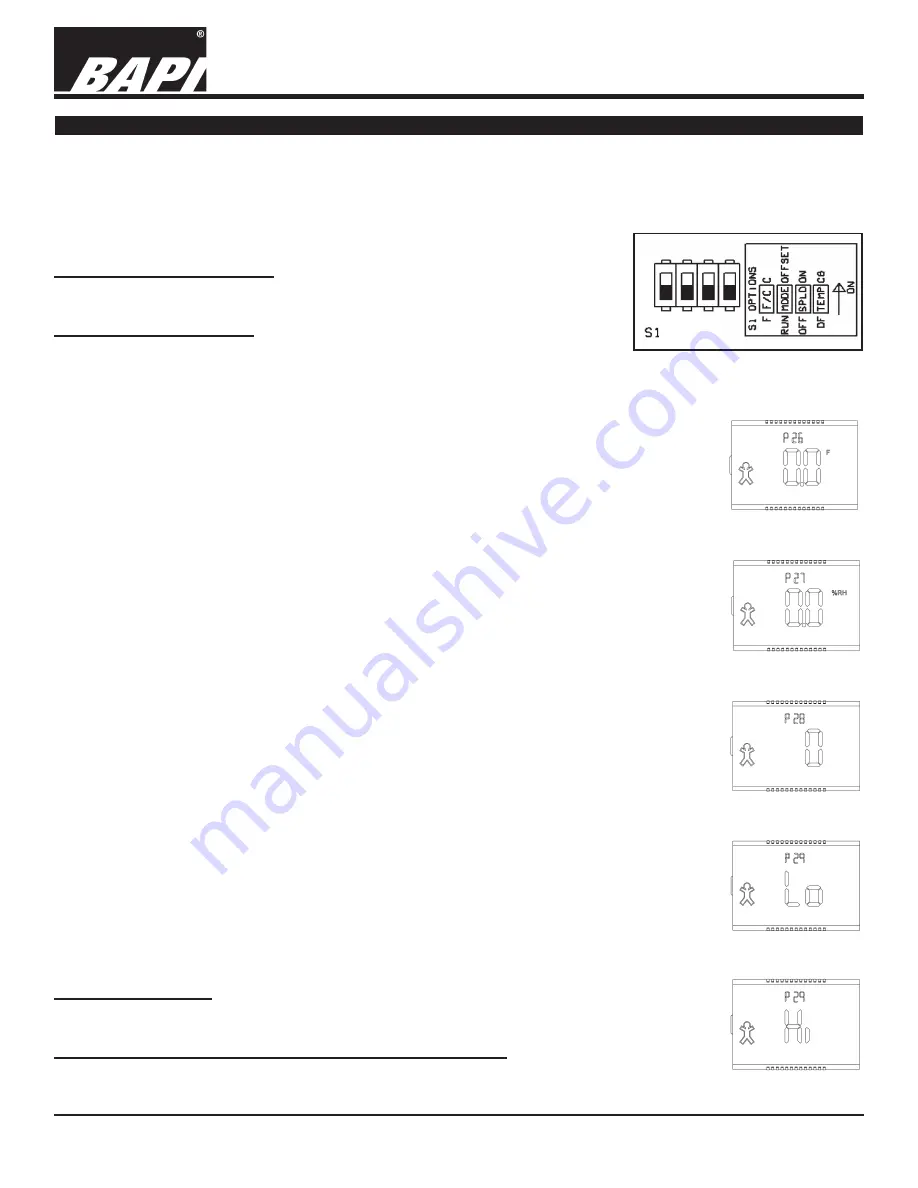
Remove cover from backplate & slide the “MODE” switch on S1 to the “OFFSET” position.
The screen in figure 11 will appear on the display. If you previously entered an offset, the offset
you entered will show on the display. Either the F or C annunciator will be lit depending on the
position of “F/C” Switch
2)
Press the Override button on the front of the sensor to advance to the screen for the parameter
you wish to change.
a. TEMPERATURE OFFSET - Screen P26 (figure 11)
b. HUMIDITY OFFSET - Screen P27 (figure 12)
c. DISPLAY MODE - Screen P28 (figure 13)
d. ACTIVE TEST & BALANCE MODE - Screen P29 (figures 14 & 15)
3)
Use the Temperature Setpoint up and down arrows on the front of the sensor to select the
calibration needed.
a. TEMPERATURE OFFSET - Adjust the temperature ± 5°in 0.1° increments
b. HUMIDITY OFFSET - Adjust the humidity ± 5% in 0.1% increments
c. DISPLAY MODE - Adjust to 0 through 7 depending on the display mode you desire.
0 - Temperature in the main portion and %RH in the upper section
1 - %RH in the main portion and Temperature in the upper section
2 - The LCD toggles the locations at a ~5 second rate
3 - Temperature Only.
4 - Setpoint Display Only (SDO), Temp Setpoint in the main portion and %RH Setpoint in
the upper section
5 - Setpoint Display Only (SDO), %RH Setpoint in the main portion and Temp Setpoint in
the upper section
6 - Setpoint Display Only (SDO), The LCD toggles the setpoints between the locations at a
~5 second rate
7 - Setpoint Display Only (SDO), Temperature Setpoint only.
(
Note: Selecting options 1, 2, 5 or 6 with units without %RH will default to mode 0
)
d. ACTIVE TEST & BALANCE MODE - Setpoint buttons up or down toggles between ‘LO’
and ‘HI’ on the LCD. This mode is active only for models which use Channel 1 as a
temperature output. ‘LO’ will drive Channel 1 to it’s lowest voltage or current output. ‘HI’
will drive Channel 1 to it’s highest voltage or current output. (figures 14 & 15)
4)
Press the Override button on the front of the sensor to ‘enter’ and store the change. Set the
“MODE” switch on S1 back to “RUN” and put the cover on the backplate.
SETPOINT LOCK OUT [SPLO Switch]
The “SPLO” Switch allows the setpoint buttons to be disabled. A switch setting of “ON” disables the
buttons.
PASSIVE TEMPERATURE SENSOR GROUNDING [TEMP switch]
Adjust DIP switch to “CG” for [TEMP –] connected to common ground [GND]
Adjust DIP switch to “DF” for [TEMP –] differential floating without connection to any ground.
The four DIP switches on the bottom of the board called S1 configure four different parameters (see Fig: 10).
1) Fahrenheit or Celsius temperature display “F/C” Switch.
2) Display Reading Offset “Mode” Switch for temperature and humidity appearance and output offset.
3) User Setpoint Lockout Enable “SPLO” Switch.
4) Passive temperature sensor differential ground or common ground configuration “TEMP” Switch.
Optional Technician Adjustments
Fig. 10: Configuration Switches S1
Fig. 11:
Temp Offset
Fig. 12:
%RH Offset
Fig. 13:
Display Mode
Fig. 14:
T&B Mode Lo
Fig. 15:
T&B Mode Hi


