background image

D

SD


Z

RIGHT

Z

LEFT


Z

LEAD


Scanner


Safety Zone (SZ)

Mobile 

Vehicle 

Mobile
Vehicle

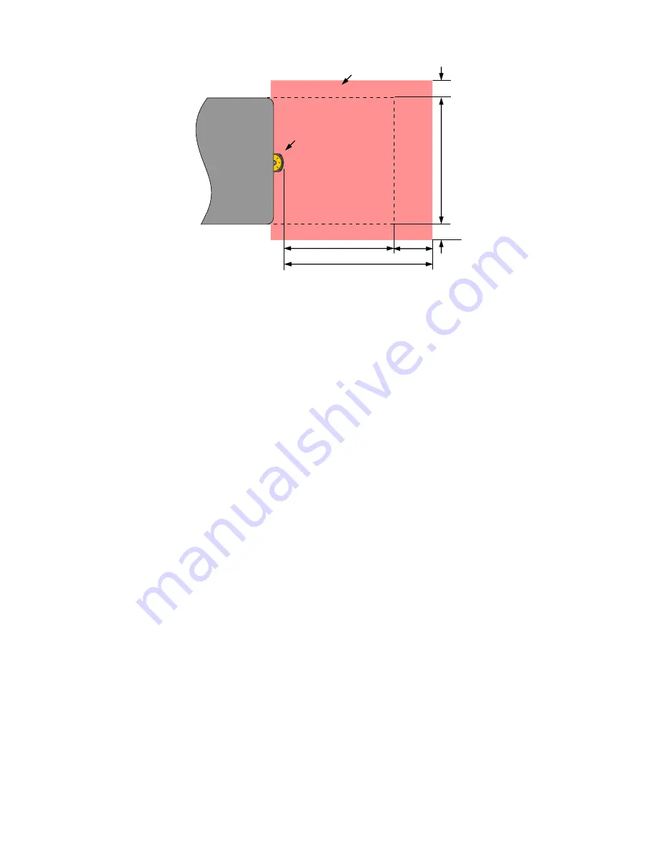
Figure 28. Calculating the minimum distance in a mobile vehicle application

D

SD

 = [V

MAX

 × (T

S

 + T

R

)] + D

B

where:

D

SD

 = Stopping distance in mm

V

MAX

 = the maximum velocity as stated by the manufacturer of the mobile vehicle

T

S

 = maximum stop time (in seconds) of the mobile vehicle (see note 1 below)

T

R

 = maximum response time (in seconds) of the Scanner (see note 2 below)

D

B

 = Braking Distance at full load and speed as stated by the manufacturer of the mobile vehicle and other

environmental factors (see note 3 below)

Notes

1. T

S

 for the mobile vehicle should be supplied by its manufacturer. T

S

 must include the response time of all devices or

controls that react to stop the vehicle (e.g., UM-FA-9A Safety Module), which are added to determine the total time

to cause braking/stopping. If all devices are not included, the calculated distance (D

SD

) will be too short and serious

injury could result.

2. Braking Distance (D

B

) should incorporate factors such as brake deterioration and environmental factors that can

impact braking (such as loose dirt/gravel, wet/moisture, icing, etc.) which can add 10% or more to the

manufacturer’s stated distance. It should be noted that braking distance is not a linear function; it increases by a

square function as velocity increases.

3.9.3 Additional Distance Factors (Z) Specific for Mobile Applications

For mobile applications, two additional factors must be considered: Z

SM

 and Z

amb

.

Z

SM

 Measurement Tolerance Factor—For Horizontal Safety Zones (parallel approach): Z

SM

 = 150 mm.

Z

amb

 Retro Reflector Factor—The additional distance needed to account for measurement errors due to light interference

(see section 3.x.4) and/or reflections from highly reflective or shiny surfaces that are present in the scanning plan.

• No ambient interference Z

amb

 = 0

• Ambient Interferences present Z

amb

 = Value interpreted from the graph based on dust filter level

Z

F

 Mobile Vehicle (AGV) Ground Clearance— The additional distance Z

F

 is required if the mobile vehicle does not have

sufficient ground clearance (HF) such that there is no space under the vehicle or Scanner for the tips of feet. If the wheels

are mounted near the side wall, always add an additional distance Z

F

 ≥ 150 mm; otherwise Z

F

 is determined according to

the following figure.


SX5 Safety Laser Scanner


www.bannerengineering.com - Tel: +1.763.544.3164

35

Summary of Contents for SX5

Page 1: ...SX5 Safety Laser Scanner Instruction Manual Original Instructions 208913 Rev A 29 November 2018 Banner Engineering Corp All rights reserved 208913...

Page 2: ...rence 26 3 2 4 Highly Reflective Backgrounds 27 3 2 5 Limited Detection Capability Zone 27 3 2 6 Dust Filtering 28 3 3 Positioning Horizontal Safety Zones for Stationary Applications 28 3 4 Minimum Sa...

Page 3: ...arning Zones 70 6 5 6 Use TEACH In to Assign Safety and Warning Zones 71 6 5 7 Protecting a Vertical Area Reference Points 71 6 5 8 Connect a Scanner to a PC Discover the Scanner 71 6 5 9 Validate and...

Page 4: ...Cleaning the Screens 90 11 4 Replace Your Scanner 90 11 5 Repairs 91 11 6 Contact Us 91 11 7 Banner Engineering Corp Limited Warranty 91 12 Standards and Regulations 92 12 1 Applicable U S Standards 9...

Page 5: ...gured and installed operational and working as intended for the application Periodically re verify as needed that the entire safeguarding system is working as intended for the application Failure to f...

Page 6: ...e safety area Within the sensing range of the scanner two areas can be monitored simultaneously one is the Safety Zone that is used to detect operators or objects entering a hazardous area the other i...

Page 7: ...ors or ignition systems can cause EMC disturbances Make no modifications to the Scanner The SX5 may not be modified or the Protective function of the Scanner can no longer be guaranteed Where changes...

Page 8: ...s functions and applications for the machine designer installer and end user Download document part number 208913 SX5 Safety Laser Scanner Checkout Procedures Instructions for daily and semi annual ch...

Page 9: ...ments Do not use the SX5 Safety Laser Scanner With any machine that can not be stopped immediately after a stop signal is issued such as single stroke full revolution clutched machinery With any machi...

Page 10: ...exceed the SX5 specifications Determine the size and coverage of the Safety Zone and Warning Zone if used depending on Physical location of the SX5 installation The minimum safety distance or the stop...

Page 11: ...Safety Zone Access to the hazard is prevented by the fencing along the side of the Safety Zone which minimizes the required floor space For this example assume a robot stopping time of 100 ms SX5 resp...

Page 12: ...an be used in conjunction with the Warning Zones If three Safety Zones are desired right left entire area then the Warning output pin is required for selecting the Zone Set Safety Zone Stationary Area...

Page 13: ...ve the plane of the Protective Field Configure any perimeter guarding systems e g an interlocked gate or safety light screen for a manual reset any reset switches must comply with the Reset Switch Loc...

Page 14: ...the Safety Zone for this example is 1666 mm 66 in which is the width of cart of 1066 mm 42 in plus the value of the two 300 mm side distances A 190 Safety Warning Zone should be used to minimize any...

Page 15: ...module response time is 25 ms The resolution can be either 40 or 70 mm since only body detection 70mm can be selected the Dpf adder is equal to 900 mm U S formula This gives a safety distance of Ds 1...

Page 16: ...must be accomplished by a Qualified Person to ensure that personnel who are exposed to potentially dangerous situations are adequately protected Features include Selecting automatic or manual start re...

Page 17: ...ommended that Reference Point Monitoring be used for all stationary applications that have surfaces that can be monitored 2 6 Passwords Improperly set parameters on the SX5 can cause serious accidents...

Page 18: ...nes to their maximum limits The configuration settings are created by a trained and Qualified Person who understands the SX5 instruction materials These settings are saved in an xml configuration file...

Page 19: ...ed space as shown by the SX5soft software 2 9 Security Protocol Certain procedures for installing maintaining and operating the SX5 must be performed by either Designated Persons or Qualified Persons...

Page 20: ...ply voltage Uv 24 Vdc 19 2 V 30 Vdc SELV PELV 2 Residual ripple 5 3 Start up current 1 0 6 A 4 The Scanner should be connected only to a SELV Safety Extra Low Voltage for circuits without earth ground...

Page 21: ...Safety protective field range 3 m 5 5 m Warning field range 40 m with remission of target 90 white Scanning angle 275 Detection capability 40 mm 70 mm Scan cycle time 30 ms Response time Programmable...

Page 22: ...inimum Distance D Safety Zone Length for Mobile Applications on page 34 Ensure that access to all hazards is not possible for all Zone Set switchover applications Ensure that safety distance and stopp...

Page 23: ...feguarding or using mechanical barriers to prevent access Behind and To the Sides of the Scanner The area behind and on either side the SX5 is not monitored It must not be possible to walk in unmonito...

Page 24: ...distance from the hazard than the calculated safety distance Enable an alternate Zone Set when the object is relocated or The moveable object must be interlocked to stop and prevent the safeguarded h...

Page 25: ...field must be used and the safety distance cannot be complied with additional supplemental safeguarding must be used To verify Safety Zone effectiveness perform a trip test A B A B 1 2 3 4 5 6 Figure...

Page 26: ...e CAUTION In all applications where strong light within 5 of the detection plane cannot be avoided apply an additional distance to the Minimum Safety Distance calculations This distance also depends o...

Page 27: ...applied to the Minimum Safety Distance calculations This distance also depends on the Dust Filter Level setting See the additional distance charts in Light Interference on page 26 minimum safety dista...

Page 28: ...ry see Highly Reflective Backgrounds on page 27 WARNING These special conditions require additional distance to be added to the Minimum Safety Distance calculations to avoid a person or object arrivin...

Page 29: ...quired before the scanners safety outputs turn off With each additional scan the response time Tr increases by 30 ms With K 1600 mm s the separation safety distance increases by 48 mm per additional s...

Page 30: ...short and serious injury could result Notes The above formula is derived from ISO 13855 2002 1 If S is greater than 500 mm then K 1600 mm s can be used instead of the 2000 mm s speed however if the 1...

Page 31: ...ns Subsequently their presence is no longer detected and the related danger becomes the unexpected start or restart of the machine while personnel are within the guarded area A pass through hazard typ...

Page 32: ...within the guarded area are not visible from the reset switch additional safeguarding must be provided as described by the ANSI B11 19 series or other appropriate standards Failure to follow these ins...

Page 33: ...lectrical drives e g servo or electrically controlled drive and braking The Safety Zone must be configured so that the mobile vehicle can come to a complete stop before a collision can occur If it is...

Page 34: ...ery flooring Absence or lack of clearance in front or to the sides of the AGV The speed of movement of an individual The reduced efficiency of the braking system due to wear WARNING Calculate the corr...

Page 35: ...loose dirt gravel wet moisture icing etc which can add 10 or more to the manufacturer s stated distance It should be noted that braking distance is not a linear function it increases by a square func...

Page 36: ...arge lateral travel 3 10 Mounting Your Scanner for Mobile Applications The mounting of the SX5 should take into account the surface contour of the path of the vehicle including holes bumps inclines ra...

Page 37: ...ied by the user If the direct mounting procedure to the back is chosen it is not possible to add the protection bracket to the device 3 10 2 Mounting the Protection Bracket The protection bracket is a...

Page 38: ...ved and only the pitch adjustment bracket 1 is used to mount the scanner To remove 6 and 8 first remove the roll adjustment screws 7 to remove the back plate 8 Then remove the four screws that attach...

Page 39: ...Fastening Screws and then the M5 Pitch Adjusting Screws do not exceed 2 5 to 3 N m torque 4 Tighten the Positioning Memory Bracket M4 screw do not exceed 1 5 to 2 N m torque 3 10 5 Adjusting the Roll...

Page 40: ...d Do not carry out any repairs to the device components Do not open the device components if the document s procedures are not followed The optics cover is an optical component Verify the optics cover...

Page 41: ...with color coded wiring referenced in this manual in compliance with the regulations and standards Attach the required cordsets to the SX5 and route the Machine Interface cable 8 pin M12 to the junct...

Page 42: ...Set 4 3 Electrical Connections to the Guarded Machine CAUTION Shock Hazard Always disconnect power from the Banner device and the guarded machine before making any connections or replacing any compone...

Page 43: ...n order to prevent the loss of the safety function Such a circuit can be described as a safe switching point Typically protective stop circuits are either single channel which is a series connection o...

Page 44: ...ation on page 32 When the SX5 is configured for Automatic Start Restart Reset to properly monitor the MPCEs an External Device Monitoring EDM function must be provided by an external means from the Sc...

Page 45: ...ed SX5 and machine may be put into service To do this a Qualified Person must perform the Commissioning Checkout Procedure described in Checkout Procedures on page 78 4 3 6 Machine Interface Connectio...

Page 46: ...2 Brown 8 Red 7 Blue 5 Grey 6 Pink 3 Green 1 White 4 Yellow 24 V dc Functional Earth 0V dc Scanner 8 pin Male Euro style face view Functionality of pins 1 3 and 4 is configured with the GUI Note This...

Page 47: ...ee WARNING UM Module Auto Reset MSC2 MSC3 S33 S34 S11 23 MSC1 MSC2 MSC3 see datasheet p n 141249 MSC Monitor Contacts or Jumper for No Monitoring 2 Brown 8 Red 7 Blue 5 Grey 6 Pink 3 Green 1 White 4 Y...

Page 48: ...Green 1 White 4 Yellow Functionality of pins 1 3 and 4 is configured with the GUI 24 V dc Functional Earth 0V dc OSSD1 OSSD2 IN1 IN2 Scanner 8 pin Male Euro style face view Single Channel Safety Stop...

Page 49: ...ntrols or actuators The machine control circuit or the safety module is not connected to the OSSD outputs at this time permanent connections will be made later The ethernet cable 4 pin M12 Euro style...

Page 50: ...erform a Trip Test Performing a trip test verifies the Safety and Warning Zone fields CAUTION Ensure that no individuals are exposed to any hazard while verifying the Safety and Warning Zones Note Alt...

Page 51: ...n A B Figure 41 Safety Zone height 8 If Zone Set switchover is used repeat steps 1 through 7 for each Zone Set that has been configured Ensure all fields correspond to the expected fields as determine...

Page 52: ...is not possible from any unprotected area Documenting safety checks in a traceable manner Immediately shutting down the machine if the safety check session reveals hypothetical faults The electrical...

Page 53: ...e scanner installation Default setting 62 ms 6 1 2 Automatic or Manual Start Restart Depending on the number of zone sets being used in the configuration the Qualified Person can select an Automatic S...

Page 54: ...n this scanner WARNING Muting Inputs Must Be Redundant Failure to follow these instructions could result in serious injury or death Do not use a single switch device or relay with two N O contacts for...

Page 55: ...in a power OFF condition Positive Opening Safety Switches Two or four independent switches each with a minimum of one closed safety contact to initiate the mute cycle are typically used An applicatio...

Page 56: ...Dependent Override Overriding a safeguarding device is the manual interruption or suspension of the normal function of a safeguard under supervisor control Typically an Override is needed to clear an...

Page 57: ...ting Function T X Bidirectional or L Unidirectional Selection The SX5 has multiple muting configurations The SX5 can monitor and respond to muting sensors in the Bidirectional or Unidirectional config...

Page 58: ...posed mode photoelectric sensors stationed on one side of the Safety Zone The muting is initiated when the two sensors are made within the configured time of each other in the proper order mute 1 then...

Page 59: ...e In addition to being able to display a graphic rendering of the monitored area the software provides configuration and management tools including file title header drop down menus function specific...

Page 60: ...Log Level Verbose Information or Error Information is the default setting Change GUI Log Options Help Laser Scanner Instruction Manual Opens the SX5 Safety Laser Scanner Instruction Manual Zip GUI log...

Page 61: ...is used for the configuration and for the safety monitoring there are different features and functions Basic The basic model allows the user to choose between the Expert and Vertical scenarios applic...

Page 62: ...ters under the Configuration header such as Name A name to identify the configuration Author A name to identify the author defaults to computer name but can be changed Description A short text descrip...

Page 63: ...unctions on page 54 Dedicated devices mute sensors must be connected to the scanner input signals to control this function The two possible settings are Disable No muting abilities Enable Muting turne...

Page 64: ...r to set the Zone Set parameters For this example the configuration includes only one Zone Set so it is not necessary to insert or edit any parameters The Input Wires parameters do not require any ass...

Page 65: ...delay default value is 30 ms It can be increased in 30 ms increments In addition factors dependent on the risk assessment that may affect the safety circuit integrity level include Analyze the means o...

Page 66: ...o switch between Zone Sets SX5soft does not obligate changing the Zone Sets sequentially i e Zone Set 1 2 3 4 etc in order therefore the user must verify that the selected passage from one Zone Set to...

Page 67: ...er direction requires two or four muting sensors be connected to the scanner inputs Unidirectional Used when objects can pass through the Safety Zone from only one direction out of the hazardous area...

Page 68: ...ld not start until the initiation button of the machine is also engaged The override time limit is 120 seconds 8 In the Input Signals section assign pins 1 3 and 4 as a Reset Restart 1 Restart 1 Reset...

Page 69: ...o different conditions specific to the application In general it is the sensitivity to various levels of airborne particles that affect the response of the scanner s detection abilities Increasing the...

Page 70: ...eturn to the previous screen 6 5 5 Create or Edit Safety and Warning Zones Figure 52 Zone Configuration screen Tools are provided to draw the Safety and Warning Zones It is possible to select differen...

Page 71: ...exit editing mode repeat this step Click the eye icon to show Zone transition points and allow the editing moving of those points After the changes are complete click the eye icon again to leave editi...

Page 72: ...lly rediscovers the scanner with the new IP Address 8 Double click on the SX5 to enter Programming Aligning IP Addresses Assuming the Subnet Mask is at the typical default setting of 255 255 255 0 the...

Page 73: ...e the display Icon Function Saves the Monitoring information into a txt file Moves the graph origin on the page After clicking on the button click and hold on the graph to move it around up down right...

Page 74: ...ess The device enters the Offline status g Click OK to continue h The software automatically rediscovers the scanner at its new IP Address Double click on the scanner to modify the configuration 3 Cli...

Page 75: ...g Technical Support and send the serial and the magic number shown The magic number is based on the run time of the scanner so this number is time sensitive To contact the Safety Application Engineeri...

Page 76: ...wse quickly the Menu functions up Button 2 to enter and confirm the selected function Button 3 to browse quickly the Menu functions down 7 2 Display Menu To enter the Display menu push the square butt...

Page 77: ...rt switch for 0 5 to 4 5 seconds and then open it Closing the reset restart switch too long causes the sensor to ignore the reset restart request 7 3 1 Reset Signal Function There are two internally c...

Page 78: ...tact Us on page 91 Checkouts must be performed as detailed and results must be recorded and kept in the appropriate place e g near the machine and or in a technical file This must include a printout o...

Page 79: ...SX5 or c Supplemental safeguarding and hard guarding as described by the appropriate safety standards are in place and functioning properly in any space between the Safety Zone s and any hazard that...

Page 80: ...from the Safety Zone verify that the machine does not automatically restart and that the initiation device s must be engaged to restart the machine b For mobile applications The vehicle stops within...

Page 81: ...ld be recorded and kept in the appropriate place e g near or on the machine in the machine s technical file Tester Qualified Person Refer to the procedure contained on the Semi Annual Checkout card Ba...

Page 82: ...ds is dangerous and could result in serious injury or death Power failures and Lockout conditions indicate a problem and must be investigated immediately by a Qualified Person A Lockout condition caus...

Page 83: ...al On Clean the window to avoid a lockout condition ITLOCK1 Normal Off Interlock waiting for a restart signal to turn the OSSDs back on INTF6 Normal On Non safety related internal test failure Reset t...

Page 84: ...owed or there are no override conditions OVERRIDE Normal On The Override function is active OVERTEMP Normal On The unit is operating above or below its allowed operating temperature range OVR TIMEOUT...

Page 85: ...or if the behavior cannot be identified Stop the machine operation if you cannot identify or locate the fault or you cannot correct the fault Secure the machine so that it cannot be unintentionally t...

Page 86: ...ent spikes and surges If random nuisance noise problems occur 1 Check for optical interference from adjacent safety laser scanners or other photoelectric sensors a Turn off the Scanner b Use a Banner...

Page 87: ...ength Style Dimensions Pinout Male STP M12D 406 1 83 m 6 ft Straight 47 4 Typ 14 5 M12 x 1 0 6g RJ45 1 White Orange 2 Orange 3 White Blue 6 Blue 4 2 3 1 1 White Orange 2 White Blue 3 Orange 4 Blue STP...

Page 88: ...Solid State Safety Outputs with Ethernet SC26 2de XS26 2de 26 convertible I O and 2 Redundant Solid State Safety Outputs with Display and Ethernet Model Description SC22 3 S 22 safety inputs 10 Auxili...

Page 89: ...et line are required See Banner datasheet p n 111881 for more information Model Description 11 BG00 31 D 024 10 amp positive guided contactor 3 N O 1 N C BF1801L024 18 amp positive guided contactor 3...

Page 90: ...a frequency depending on the surrounding environmental conditions and using the recommended materials Use only the cleaning kit specified consisting of approved cleanser and cleaning cloths Do not use...

Page 91: ...bility for misuse abuse or the improper application or installation of the Banner product THIS LIMITED WARRANTY IS EXCLUSIVE AND IN LIEU OF ALL OTHER WARRANTIES WHETHER EXPRESS OR IMPLIED INCLUDING WI...

Page 92: ...ines ANSI B11 15 Pipe Tube and Shape Bending Machines ANSI B11 16 Metal Powder Compacting Presses ANSI B11 17 Horizontal Extrusion Presses ANSI B11 18 Machinery and Machine Systems for the Processing...

Page 93: ...he Human Body ISO 14119 EN 1088 Interlocking Devices Associated with Guards Principles for Design and Selection EN 60204 1 Electrical Equipment of Machines Part 1 General Requirements IEC 61496 Electr...

Page 94: ...blocked condition occurs OSSD1 and OSSD2 outputs simultaneously turn off within the system response time Brake A mechanism for stopping slowing or preventing motion C Cascade Series connection or dais...

Page 95: ...either no effect or a Lockout condition are permitted failures which cause an unsafe condition a failure to danger are not Banner safety products are extensively FMEA tested G Guarded Machine The mac...

Page 96: ...y off when the object is removed from the defined area To re energize the outputs perform a proper manual reset Minimum Object Sensitivity MOS The minimum diameter object that a safety light screen sy...

Page 97: ...ed The machine cycle runs to completion and the operator can then insert a new part and start another cycle The presence sensing device continually guards the machine Single break mode is used when th...

Page 98: ...Specified Test Piece An opaque object of sufficient size used to block a light beam to test the operation of a safety light screen system When inserted into the defined area and placed in front of a b...

Reviews: