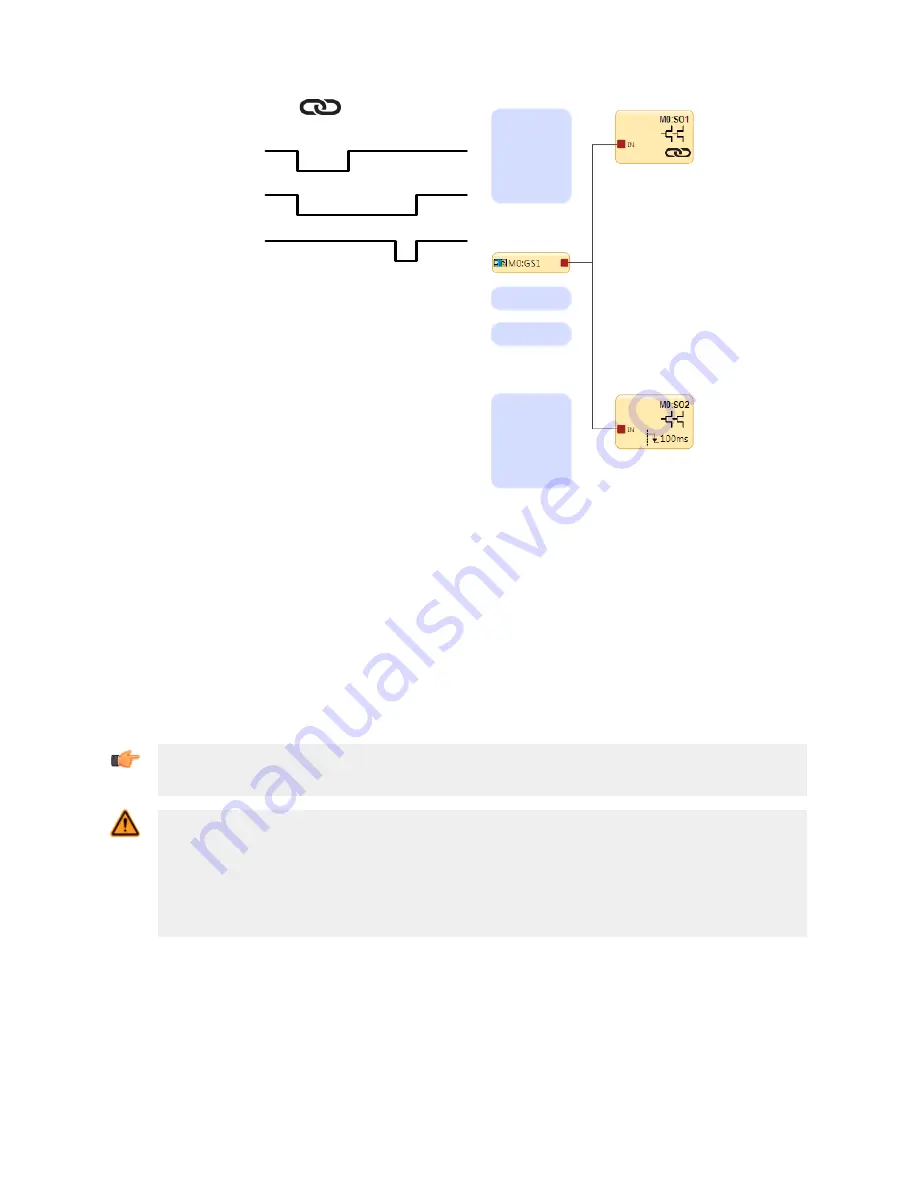
GS
SO1
SO2
Figure 66. Timing Diagram—Linked Safety Outputs
6.6.1 Solid-State Safety Outputs
The solid-state Safety Outputs, for example, SO1a and b, and SO2a and b, are actively monitored to detect short circuits
to the supply voltage, to each other, and to other voltage sources and are designed for Category 4 safety applications. If a
failure is detected on one channel of a safety output pair, both outputs attempt to turn Off and will enter a lockout state.
The output without the fault is able to turn off the hazardous motion.
Similarly, a Safety Output that is used individually (split), is also actively monitored to detect short circuits to other power
sources, but is unable to perform any actions. Take extreme care in the wiring of the terminals and in the routing of the
wires to avoid the possibility of shorts to other voltage sources, including other Safety Outputs. Each split Safety Output is
sufficient for Category 3 applications due to an internal series connection of two switching devices, but an external short
must be prevented.
Important: When Solid-State Safety Output modules (XS2so or XS4so) are used, the power to those
modules must be applied either prior to or within 5 seconds after applying the power to the Base
Controller, if using separate power supplies.
WARNING: Single Channel (Split) Outputs use in Safety Critical Applications
If a single channel output is used in a safety critical application then fault exclusion principles must be
incorporated to ensure Category 3 safety operation. Routing and managing single channel output wires
so shorts to other outputs or other voltage sources are not possible is an example of a proper fault
exclusion method. Failure to incorporate proper fault exclusion methods when using single channel
outputs in safety critical applications may cause a loss of safety control and result in a serious injury or
death.
Whenever possible, incorporating External Device Monitoring (EDM) and/or Adjustable Valve Monitoring (AVM) is highly
recommended to monitor devices under control (FSDs and MPCEs) for unsafe failures. See
on page 90 for more information.
Output Connections
The Safety Outputs must be connected to the machine control such that the machine’s safety related control system
interrupts the circuit or power to the machine primary control element(s) (MPCE), resulting in a non-hazardous condition.
When used, Final Switching Devices (FSDs) typically accomplish this when the safety outputs go to the Off state. Refer to
the
on page 11 before making connections and interfacing the Controller to the machine.
XS/SC26-2 Safety Controller
87


