Quick Start Guide
Introduction
The iVu Plus TG Gen2 Series Sensor is used to monitor labels, parts, and packaging for type, size, orientation, shape, and
location. The sensor has an integrated or remote color touch screen display making installation, setup and configuration
easy without requiring a PC.
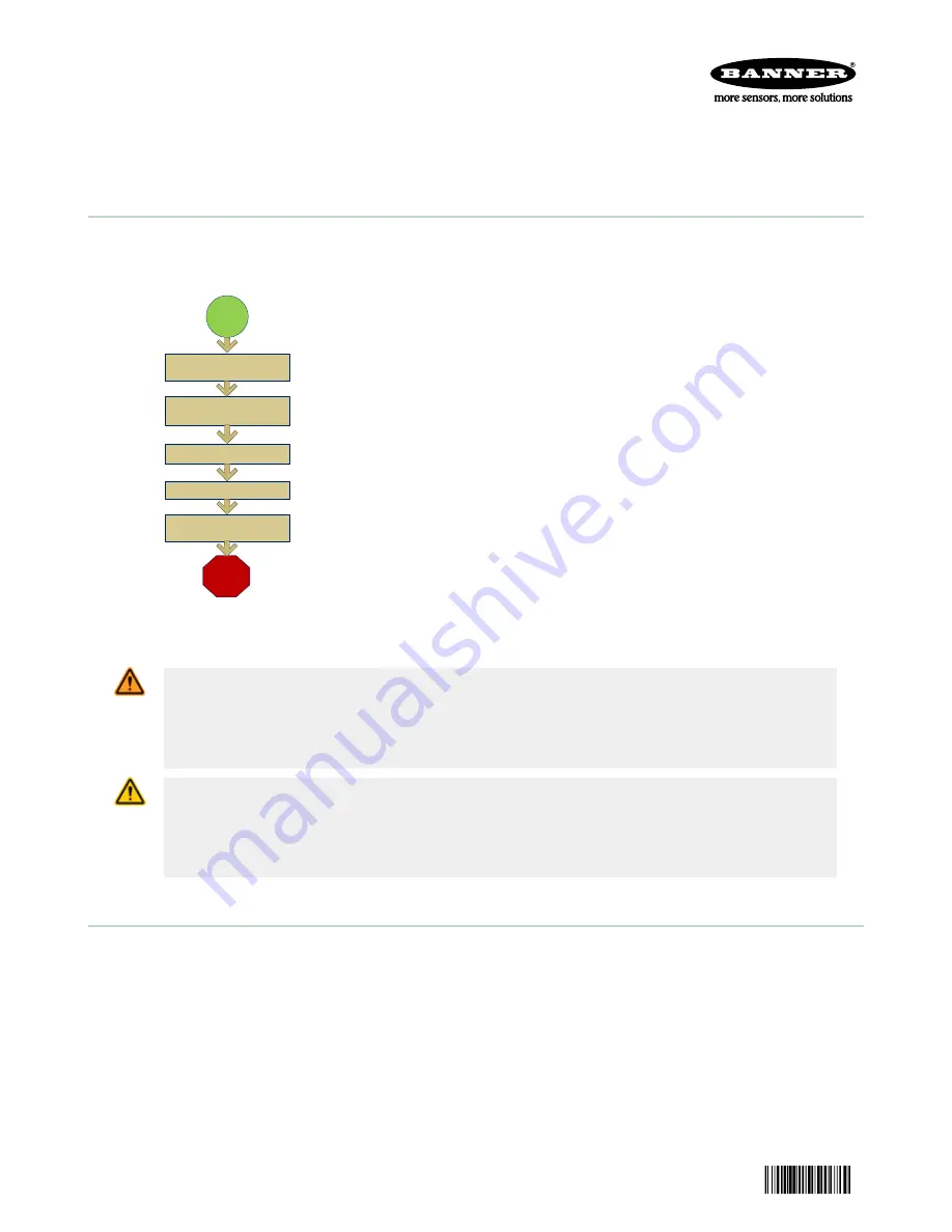
Finish
Set Sensor Parameters
Start
Install and Connect the
Sensor
Initial Boot into Demo Mode
Select Sensor Type
Acquire A Good Image
Quick Start Overview
This guide is designed to help you set up and install the iVu Plus TG. It
provides an overview of the sensor and illustrates how to set up the sensor
to inspect a label, part, or packaging. The flow chart to the left provides an
overview of the process.
Use of this document assumes familiarity with pertinent industry standards
and practices.
For complete information on programming, performance, troubleshooting,
dimensions, and accessories, please refer to the documentation listed below.
This documentation is available on the Product CD or at
. Search for the part number to view the
documentation.
•
iVu Plus TG Gen2 with Integrated Display (datasheet; P/N 179044)
•
iVu Plus TG Gen2 with Remote Display (datasheet; P/N 179045)
•
iVu Plus TG Gen2 Instruction Manual (P/N 179042)
•
iVu Plus Industrial Ethernet User's Guide (P/N B_3095133)
In addition, the sensor includes integrated Help.
WARNING: Not To Be Used for Personnel Protection
Never use this device as a sensing device for personnel protection. Doing so could lead to
serious injury or death. This device does not include the self-checking redundant circuitry necessary
to allow its use in personnel safety applications. A sensor failure or malfunction can cause either an
energized or de-energized sensor output condition.
CAUTION: Electrostatic Discharge
Avoid the damage that electrostatic discharge (ESD) can cause to the Sensor.
Always use a proven method for preventing electrostatic discharge when installing a lens or attaching a
cable.
Installing and Connecting the Sensor
The iVu Plus TG sensor requires a bracket for mounting. Three brackets are available from Banner. The brackets allow the
sensor to be mounted either perpendicular to the part or at an adjustable angle.
Thread three M4 x 4mm screws through the bracket into the mounting holes in the bottom of the sensor. Tighten all three
screws.
iVu Plus TG
Gen2
Series Sensor
Original Document
178442 Rev. B
9 September 2014
178442


