


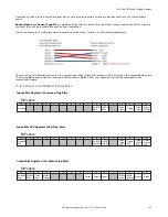

9.3.1 General Command Execution
Point of View of PLC
Start
(Optional)
If using Command
ID, set it and its
Parameter value
as required
Done
Read Error Code.
Handle error
condition.
Clear all
Output Flags
Is Execution
Error flag set?
Command execution
successful. Read value
and input status flags as
required
ACK Flag set?
Set Command
Output Flag
Yes
No
Yes
No
Following rules apply for the usage of input bit
commands:
•
Only one iVu input bit can be set at a time.
•
Corresponding ACK bits are only set high on
completion of the command (if the iVu input bit
is still high).
•
Corresponding ACK bits are cleared when the iVu
input bit is cleared.
•
When multiple iVu input bits are set
simultaneously, the Execution Error input bit is
set and an Error Code value is reported in the
Error Code register.
•
The Execution Error iVu output bit is cleared
when all ACK bits get cleared, or a new valid
command is received.
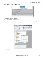
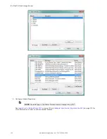
9.4 EtherNet/IP
The iVu Plus device is controlled via EtherNet/IP using assembly objects. From the point-of-view of a PLC, there are three
input assemblies and two output assemblies.
The Originator of the EtherNet/IP connection is the PLC. The Target of the EtherNet/IP connection is the iVu Plus. The
direction of communication can be described as T > O or O > T (sometimes also shown as T2O or O2T).
iVu Plus TG Gen2 Image Sensor
www.bannerengineering.com - Tel: 763.544.3164
109