background image

3 Display Modes

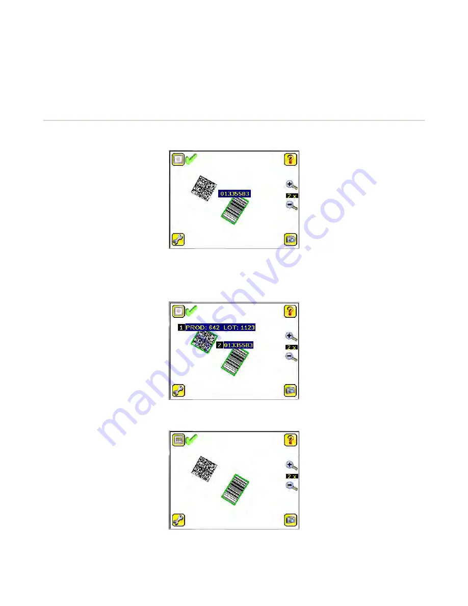
In the upper left of the screen is an icon for accessing different Display Modes:

Display Annotations

Hide Annotations

Display Statistics.

3.1 Display/Hide Annotations

Click the icon in the upper-left of the screen to display annotations. When annotations are on, the display shows the data

the sensor has read.


If the sensor reads more than one barcode in the field of view (FOV), in addition to the read data, the display indicates the

index of each read barcode. In the example below, the top barcode is 1 and the bottom barcode is 2. It is important to

note that, if the sensor reads more than one barcode, only the first barcode data (index #1) can be compared or used in a

remote teach operation


Click the icon in the upper-left of the screen to hide annotations.


iVu Barcode Reader (BCR)


37


Summary of Contents for IVU BCR Series

Page 1: ...iVu Barcode Reader BCR Instruction Manual Original Instructions B_089425 Rev B 18 March 2014 ...

Page 2: ... 3 Communication Logs 36 3 Display Modes 37 3 1 Display Hide Annotations 37 3 1 1 Inspection Statistics 38 4 Setting up an Inspection 40 4 1 Acquiring a Good Image 40 4 2 Setting Up a Barcode Application 42 4 3 Setting up for Data Compare 43 5 Communications Guide 45 5 1 Command Channel 45 5 2 Setting Up Serial Communications 46 5 3 Testing and Troubleshooting iVu Command Channel Communications 47...

Page 3: ...How to Round Trip Debug Using the Emulator 61 6 2 1 How to Debug Using the Emulator from a PC 61 6 2 2 How to Debug Using the Emulator from the USB Flash Drive 62 7 Updating the Sensor 63 7 1 Update Process 63 7 2 How to Set or Modify a Device Name 63 7 3 How to Reset the Sensor Password 64 7 4 How to Use Bitmap Image Files with the iVu Emulator 64 8 LED Indicator Troubleshooting 66 8 1 Errors 66 ...

Page 4: ...13 EAN8 UPCE Postnet IMB and Pharmacode 1 1 Installation 1 1 1 Components iVu with Integrated Display The iVu Series sensor comes fully assembled with the lens and an integrated ring light if so ordered The integrated touchscreen display has a plastic cover to protect the display Remove this cover when setting up the sensor When the display is not in use be sure to keep the display covered to prot...

Page 5: ...ting in external trigger mode requires a triggering source for example the Banner WORLD BEAM QS18VN6D sensor 1 Focusing Window 2 Focusing Window Locking Clip 3 LED Green Ready Red Error 4 LED Green Pass Red Fail C A B A USB Connector B Remote Display Connector C Power I O Connector Mounting Bracket Mounting Holes uses supplied three M4 x 4 mm screws 1 1 2 Cable Connections Cable Connections for iV...

Page 6: ...round Output 12 Violet RS 232 Rx Input Cable Connections for the iVu BCR with a Remote Display The cable connections on the iVu sensor are shown below and power I O connections B are defined in the Power I O Connections table below A Remote Display Connector B Power I O Connector C USB Connector NOTE Micro video lens model shown C Mount model connections are identical Power I O Connections Pin Wir...

Page 7: ...ansition This setting can be changed in the Main Menu System Discrete I O Input Polarity screen on the sensor PNP Low to High Trigger and Remote Teach Input Waveforms Power up Trigger Remote Teach Pink Wire Color Function Gray The sensor triggers from low to high and Remote Teach behaves electrically like trigger NPN High to Low Trigger and Remote Teach Input Waveforms Trigger Remote Teach Pink Wi...

Page 8: ...il Pass Function Strobe Out Configure as External Expose Based Outputs 1 2 and 3 Set as Active Pass Outputs 1 2 and 3 Set as Active Fail Figure 1 PNP Outputs Ready Pass Fail Pass Pass Fail Pass Strobe Out Configure as External Expose Based Outputs 1 2 and 3 Set as Active Pass Outputs 1 2 and 3 Set as Active Fail Function Figure 2 NPN Outputs 1 1 3 Installing and Connecting the Sensor The iVu BCR s...

Page 9: ...ndow B When removing the window the Locking Clip will be loose Be careful not to lose the clip while removing the window 2 Unscrew the Focusing Window by turning it clockwise approximately 5 complete turns or until the Focusing Window disengages from the light lens assembly NOTE The light lens assembly may include an integrated ring light or a blank disk if an integrated ring light is not used Be ...

Page 10: ...sensor C Mount Lens Models D C A B E C A C Mount Lens B Lens Enclosure C Retainer Ring optional D Filter optional E Filter Retainer Ring Tool NOTE Filter Kits are available separately 1 Remove the Lens Enclosure and Lens 2 Install filter behind the retainer ring Make sure it is fully seated 3 Using the provided retainer ring tool thread the retainer ring into the sensor until it firmly seats the f...

Page 11: ...sensor reboot or the last time the statistics were reset including Count Range minimum and maximum number of objects observed Passed running total of parts that passed inspection Failed running total of parts that failed inspection Missed triggers running total of missed triggers Time Range minimum and maximum inspection times observed Click the Reset button to reset statistics Inspection Results ...

Page 12: ...n the required number of barcodes are found but the compare is not successful 1 3 2 Trigger Modes The iVu BCR has four trigger modes that determine how the sensor captures and processes images External Single Continuous External Gated Command 1 3 3 Compare Data The iVu BCR has a data compare feature for comparing read barcode data against reference data Data can be manually entered by navigating t...

Page 13: ...s a method of remotely updating inspection parameters while the iVu sensor is running The sequence of events for executing a Remote Teach are 1 With the sensor Ready see Installation on page 4 pulse the Remote Teach line 2 The sensor recognizes that the Remote Teach line has been pulsed and waits for the next valid trigger 3 At the next valid trigger Ready goes inactive the Green Ready LED shuts O...

Page 14: ...ked Sensor Menus View Logs Setup Command Channel View Logs Setup Select Add New Startup Delete Stored Inspections Inspection Properties Scan Time Limit Inspection Name Barcode Barcode Type Barcode Count Data Compare Compare Set Data Inspection ID Set Name ID System Live Mode Demo Mode Sensor Information Sensor Mode Save to USB Load from USB Reset to Defaults Sensor Configuration Lock Sensor Ethern...

Page 15: ...e is powered up it starts in Demo Mode Demo Mode uses stored images and inspection parameters that demonstrate how the sensor is set up without having to worry about focus lighting or triggers In this mode practice making adjustments while observing how the adjustments affect the results To exit Demo Mode go to Main Menu System Sensor Mode and select Exit Demo Mode Upon exit the sensor reboots int...

Page 16: ...ion Main Menu System Sensor Information The Information screen displays the following sensor information Serial Number Firmware Version Boot Number Up Timer the time elapsed since last boot of the sensor Hour Count the total hours of operation in the sensor s lifetime Model Number Device Name Click the right arrow next to the Sensor Name field to display a software keyboard that allows you to chan...

Page 17: ... for data export only NOTE Either Data Export Channel OR Command Channel can be enabled at a time Serial I O Main Menu System Communications Serial I O Set Serial I O settings for Baud Rate Data Bits Parity Control and Stop Bits on this screen Clicking Status displays recent bytes transmitted through this channel Port Status Main Menu System Communications Serial I O Status The Port Status screen ...

Page 18: ...ications Data Export Connection The Connection screen is used to enable or disable the Data Export Channel Data To Export Main Menu System Communications Data Export Data To Export The options in the Data To Export screen are used to determine what barcode data is exported via the serial port NOTE Grab the edge of the Data to Export menu and pull down to allow all information to show iVu Barcode R...

Page 19: ...in Menu System Communications Command Channel Connection The Connection screen is used to enable or disable the Command Channel Delimiters Main Menu System Communications Command Channel Delimiters In the Delimiters screen there are three delimiter options that you can set Field Delimiter which determines what is used to separate data that the sensor is sending out to a remote device End of Frame ...

Page 20: ... is dependent on the Input Polarity setting Low To High The Trigger and Remote Teach are detected on a low to high transition of the signal High To Low The Trigger and Remote Teach are detected on a high to low transition of the signal The default setting for a PNP sensor is Low To High and for an NPN sensor it is High To Low The user can change the setting on the Input Polarity screen Input Pullu...

Page 21: ...mpared If the sensor is using Data Compare Fail indicates that either no good barcode was found or the data did not compare A Match condition occurs when the required number of barcodes are found and the compare is successful A No Match condition occurs when the required number of barcodes are found but the compare is not successful A Missed Trigger condition occurs when a trigger is received whil...

Page 22: ...splay optimization can be enabled in the Advanced menu Fail Hold Time Main Menu System Display Settings Fail Hold Time The Fail Hold Time determines how long a failed image is displayed on the LCD so that you can see what failed The sensor will continue to process any triggers and the inspection will continue normally This time delay is just for the screen You can set this parameter from 0 to 3600...

Page 23: ...e long and or no idle time exists between inspections Disable this feature if Missed Triggers occur due to touchscreen presses With this setting disabled the display may become sluggish when the sensor is busy 2 2 8 Reboot Sensor Main Menu System Reboot Sensor The Reboot Sensor screen allows you to force a reboot of the sensor NOTE This option is not available on the Emulator 2 2 9 Firmware Update...

Page 24: ...Increasing the exposure time by moving the slider to the right allows more light to energize the imager which brightens the image NOTE This feature is not effective on the emulator 2 3 3 Gain Main Menu Imager Gain Gain is an electronic boost to the image signal Increasing Gain by using the right arrow key or moving the slider to the right increases image brightness without increasing exposure time...

Page 25: ...r uses internal timing to continuously capture images For each captured image the sensor scans through the configured barcode types looking for the specified number of barcodes If the specified number of barcodes is found a Read event occurs If the specified number of barcodes is not found the sensor captures another image and repeats the scan There are two parameters that are used to fine tune ho...

Page 26: ...ds through the command channel 2 3 5 Focus Main Menu Imager Focus The Focus Number displayed at the bottom of this screen is used to fine tune image focus Loosen the lock on the lens cover turn the focus ring on the sensor until the Focus Number peaks or the image appears sharp then lock the focus ring NOTE For the Focus Number to work the sensor must be triggering and the images must be similar o...

Page 27: ...ays ON option is not available 2 3 7 FOV Field of View Main Menu Imager FOV The field of view FOV is the area that the sensor can see at a given working distance The working distance is the distance from the sensor s lens cover to the part being inspected By default the sensor uses the entire FOV in its operation The effective FOV can be reduced in order to speed up the processing time of an inspe...

Page 28: ...spection parameters on currently running inspection and manage stored inspections 2 4 1 Barcode Menu Main Menu Inspection Barcode The Barcode Menu is the location for Barcode Type Barcode Count and Data Compare screens Barcode Type Main Menu Inspection Barcode Type The first time the sensor is powered up the selection checkboxes for DataMatrix and All Linear barcode types are checked The best prac...

Page 29: ...fections The Fast setting has the best results on high contrast images that contain high quality barcodes When you select Robust the sensor uses an algorithm that performs routines to correct for imperfections of the barcode image When Equalization is selected the sensor tries to improve the contrast within the symbol to improve readability Dotpeened Enabling Dotpeened causes the decoder to be run...

Page 30: ... Code Settings QR Code Type The QR Code Type determines whether the device should decode a QR Code Micro QR code or both Unicode The device is capable of decoding Kanji characters embedded in a QR Code In order for the device to display the decoded data correctly and be able to export the decoded data in Unicode format 2 byte this setting should be enabled Decoded data sent out on Communication Ch...

Page 31: ...e Settings Scan Direction For Pharmacode select one of the following for Line Scanning Left to Right Right to Left Top to Bottom Bottom to Top Omnidirectional Use Omnidirectional scanning if barcode can appear inverted on part being inspected If Compare is enabled the sensor attempts to compare that string to decoed data in both scan directions Inspection is marked as PASS if at least one string m...

Page 32: ... if there is one of each of these types in an image and the Barcode Count is set to 3 the sensor will decode all three however if there are three IMB barcodes for example the sensor will always only decode one IMB barcode Data Compare Main Menu Inspection Data Compare The menu options here are used to set up the sensor for Data Compare Note that if the Barcode Count is greater than 1 only the firs...

Page 33: ...l change to green with a slash through it If you want to unmask a character make sure that the cursor is to the left of the masked character and click the Unmask button Edit Compare Data The Edit screen displays data that was previously read or entered in the text field The Position of the cursor within the characters displayed in the text field is indicated at the top of the screen Additionally t...

Page 34: ... if the new data is of the same length as the previous input data If the length does not match masking is removed 2 5 Logs Menu Main Menu Logs The Logs menu icon is on the Main Menu and is used to set up view and save Inspection and System Logs 2 5 1 Inspection Logs Main Menu Logs Inspection Logs This menu provides for configuring and viewing Inspection Logs Inspection Logs are stored inspection r...

Page 35: ...he View Inspection Log screen is used to debug an inspection and shows one inspection in read only mode Click the upper left icon to cycle through views When in Statistics view the table title has arrows to switch between Inputs and Results of the Inspection Use the left and right arrow keys at the bottom of the screen to navigate through the all stored Inspection Logs Setup Main Menu Logs Inspect...

Page 36: ...ges while in Demo mode Additionally the Emulator does not log changes 2 5 3 Communication Logs Main Menu Logs Communication Logs The Communication Log contains logs for the two communications channels Command Channel and Data Export The features below are available for each of the logs Click the icon in the upper left corner of the screen to show hide the time column Click Clear Log button at the ...

Page 37: ...e data the sensor has read If the sensor reads more than one barcode in the field of view FOV in addition to the read data the display indicates the index of each read barcode In the example below the top barcode is 1 and the bottom barcode is 2 It is important to note that if the sensor reads more than one barcode only the first barcode data index 1 can be compared or used in a remote teach opera...

Page 38: ...ion Missed triggers running total of missed triggers Time Range minimum and maximum inspection times observed Click the Reset button to reset statistics Inspection Results The Inspection Result screen shows data about the current inspection being viewed including the last Frame number Barcode Count Inspection Time read Barcode Data Barcode Viewer To view detailed information about a particular bar...

Page 39: ...o text boxes The upper one displays the data read from the barcode and the lower text box shows the data from the Data Compare screen The sensor does a position by position match and the characters that match are in yellow and mismatches are in red iVu Barcode Reader BCR 39 ...

Page 40: ...g that optimizes its contrast and separates it from the background Depending on the target this may mean the integral ring light is not the best choice and other Banner lights should be considered Adjust the mounting angle to provide the clearest image of the barcode The mounting bracket lets you easily position and adjust the sensor on your line Typically a slight angle will help with read robust...

Page 41: ...uses on closer objects while turning the Focusing Window clockwise focuses on more distant objects 3 After the best image has been acquired lock the focusing window Micro Video Lens Models A Lens B Focusing Window C Locking Clip D Locking Screw E Filter Cap optional F Filter optional NOTE Filter Kits are available separately For C Mount Models Only 1 Remove the Lens Enclosure 2 Adjust focus while ...

Page 42: ...ypes listed for All Linear uncheck the box next to All Linear and select a radio button next to the desired linear barcode type If you use only DataMatrix uncheck all the boxes except the one next to DataMatrix 2 Go to Main Menu Inspection Barcode Count to select the number of barcodes 1 to 10 to be read at one time After the sensor has been set up as described Each successfully read barcode is ma...

Page 43: ... iVu BCR sensor to compare decoded barcode data against some reference For this example the reference data will be from a previously decoded barcode 1 Go to the Main Menu Inspection Data Compare Compare to Enable data compare 2 Go to the Main Menu Inspection Data Compare Set Data and click the Show last read data button 3 Press the Yes button 4 Press the Home icon to return to the main screen iVu ...

Page 44: ...For all subsequent triggers when the sensor reads the barcode data it will compare it against this reference data iVu Barcode Reader BCR 44 ...

Page 45: ...quest Frame D iVu BCR Sensor The following are some of the functionality available via the command channel Get sensor information such as version and sensor name Control discrete I O such as trigger and teach Get sensor results such as sensor status Set and get BCR compare strings Command Channel Sample Application The iVu BCR installation CD has a Command Channel sample application that provides ...

Page 46: ...l Ground 12 Violet RX 2 Enable the command channel Go to Main Menu System Communications Command Channel Connection 3 Configure port settings baud rate data bits parity and stop bits on the iVu to match the settings on the control device Go to Main Menu System Communications Serial I O 4 Configure end of frame delimiters Go to Main Menu System Communications Command Channel Delimiters Valid end of...

Page 47: ...the Port Status screen go to Main Menu System Communications Serial I O and click on the Status button The upper field shows the bytes received request frame on the iVu from the control device The lower field shows the bytes sent response frame from the iVu to the control device Port Errors The Port Errors screen can help to debug communications channel issues Parity Break and Framing indicate mis...

Page 48: ...yed error count will increment by one If the command takes a long time to process the last long entry will change to an hourglass for example during trigger of long inspections 5 3 3 Using the iVu Command Channel Sample Application or a Terminal Program for Testing The easiest way to test that the iVu command channel is correctly receiving and transmitting data is to use either the iVu Command Cha...

Page 49: ...he settings on both devices match exactly 5 3 5 Verifying Basic Transmit Functionality The iVu command channel will only send response frames to the requesting device if it receives a valid end of frame delimiter from the requesting device To verify transmit functionality 1 Transmit an end of frame delimiter sequence from the requesting device to the iVu sensor For example in a terminal program si...

Page 50: ...are displayed in hex notation x0D 5 4 1 Command Flow The command flow should be such that a new command request should not be issued until the iVu command channel acknowledges the previous command request For example the following is a series of command requests and responses The first request sets the trigger mode to command and once the sensor responds with an OK the next command request is issu...

Page 51: ...nd Group Description CompanyName Info The company name as a string ModelNumber Info The sensor model number as a string FirmwareVersion Info The sensor firmware version as a string SerialNumber Info The sensor serial number as a string Name Info The sensor name as a string BootNumber Info The number of sensor bootups UpTimer Info The elapsed time the sensor has been running in the format hh mm ss ...

Page 52: ...tart and end with the double quote character CompareMask BCR_INPUT The compare string mask in binary format that is masked characters are indicated by a 1 and unmasked characters are 0 Note that the mask character string must match the length of the compare string Count BCR_RESULT The total number of barcodes found in the last inspection Data BCR_RESULT The barcode data strings that were read in t...

Page 53: ...the form ERROR nnnnn_ERROR_IDENTIFIER for example ERROR 10001_COMMAND_NOT_RECOGNIZED Refer to Command Channel Error Codes on page 59 for a list of errors 5 5 Examples 5 5 1 Conventions Used for Examples There are a number of command channel examples included here and the following are the conventions used in the examples All examples use CR LF for the end of frame delimiter and this delimiter is a...

Page 54: ...OK x0D x0A 0043000011201 x0D x0A 5 5 3 How to Modify Barcode Compare Data Using the Command Channel 1 Main Menu System Communications Command Channel Connection and select Enabled 2 Set Trigger to Command Go to the Main Menu Imager Trigger screen and from the drop down select Command 3 Set the compare data set bcr_input comparedata 0043000011201 x0D x0A OK x0D x0A 4 Trigger the sensor do trigger x...

Page 55: ...ompare string mask Masked characters need indicated by a 1 and unmasked characters are 0 and the mask character string must match the length of the compare string Examples get bcr_input comparedata x0D x0A OK x0D x0A 0043000111201 x0D x0A get bcr_input comparemask x0D x0A OK x0D x0A 1111000000000 x0D x0A set bcr_input comparedata 0043000111201 x0D x0A OK x0D x0A set bcr_input comparemask 111100000...

Page 56: ... mininspectiontime Returns the minimum elapsed time of the inspection get history maxinspectiontime Returns the maximum elapsed time of the inspection get history minbarcodecount Returns the minimum number of barcodes read get history maxbarcodecount Returns the maximum number of barcodes read do history clear Clears all history fields for example pass fail etc Examples get history passed x0D x0A ...

Page 57: ...ote display get info remotemodelnumber Returns the model number of the remote display Examples get info companyname x0D x0A OK x0D x0A Banner Engineering Corp x0D x0A get info bootnumber x0D x0A OK x0D x0A 42 x0D x0A get info uptimer x0D x0A OK x0D x0A 4 42 42 324 x0D x0A 5 6 5 Inspection Command Group Command Group Item Description get inspection status Returns either Pass Fail or Idle get inspec...

Page 58: ...nspection and configuration parameters Blocks until finished Should be used sparingly do system reboot Reboots the sensor Pre empts all commands except save do system save x0D x0A OK x0D x0A 5 6 8 Teach Command Sets the sensor to teach on the next trigger Example do teach x0D x0A OK x0D x0A 5 6 9 Trigger Command Group Command Group Item Description set trigger mode Sets trigger mode to one of the ...

Page 59: ...nd any arguments and an end of frame delimiter 10001 COMMAND_NOT_RECOGNIZED The command specified is not recognized 10100 GROUP_MISSING A Group ID must be specified immediately after the command 10101 GROUP_NOT_FOUND The specified Group ID is invalid unknown 10102 GROUP_ITEM_MISSING A Group Item ID must be specified immediately after the Group ID 10103 GROUP_ITEM_NOT_FOUND The specified Group Item...

Page 60: ...ABLED Operation requires Barcode compare to be enabled 20003 COMPARE_MASK_INVALID Compare mask invalid Expecting string of 1 s and 0 s with length equal to compare data string 20004 NUMBER_TO_FIND_NOT_ONE Barcode number to find must be set to one for this operation 80000 REMOTE_DISPLAY_NOT_CONNECTED Remote Display must be connected to obtain this value 80001 REMOTE_DISPLAY_NOT_SUPPORTED This senso...

Page 61: ...Using the Emulator from a PC 1 Plug a USB Thumb Drive into the sensor 2 Save Inspection Logs to the Thumb Drive a On the Main Menu Inspection Logs View Logs screen click the Save icon to save the inspection logs b When prompted select Yes to save sensor configuration along with the Inspection Logs The location of these files on the USB Thumb Drive will be displayed after the operation is completed...

Page 62: ... saved in USB BANNER SENSOR_NAME For example if the sensor name is myName Configuration File CONFIG CFG path USB BANNER myName Inspection Logs path USB BANNER myName InspLog NOTE If the sensor has no name the folder name is the first 8 characters of the serial number 3 Remove the USB drive from the sensor and insert it into an available USB port on a Windows PC that has the iVu Emulator installed ...

Page 63: ...copy the selected firmware to the USB Thumb Drive Step 2 Install firmware on iVu 1 Remove the USB Thumb Drive from the PC and plug it into the sensor 2 On the sensor select System Firmware Update The name of the firmware file you copied on the USB Thumb Drive will be displayed 3 Choose correct file and click on the Load button 4 Follow the steps on the screen to update the firmware 7 2 How to Set ...

Page 64: ...r you can remove the current password using a reset key that is generated by the Password Reset Utility which is located on the Product CD The following steps will guide you through the specific steps to reset the password 1 On your iVu Series sensor click the Forgot button located on the bottom of the Enter Current Password screen 2 Write down the 6 digit Device Key 3 On a Windows PC insert the i...

Page 65: ...in Menu Image Trigger and select Internal 4 Set the Trigger Interval as desired The iVu Emulator will be running using the bmp files from Step 1 NOTE Banner does not recommend setting up inspections using these 8 bit grayscale images because you will always end up modifying the configuration after loading it on the sensor on the line A better choice would be to set up the inspection on the emulato...

Page 66: ...occurring Reboot the sensor The Power LED is lit steady red These type of errors are reported in the System log and appear highlighted in red Do the following 1 Look in the System Log to see the error 2 Clear the LED that is go to the Main Menu Logs System Logs and press the Clear System Error button at the bottom of the screen a sensor reboot is not required 3 If the error occurs again you can tr...

Page 67: ...device it contains no field replaceable components If the device or a device component is determined to be defective by a Banner Applications Engineer they will advise you of Banner s RMA Return Merchandise Authorization procedure Important If instructed to return the device pack it with care Damage that occurs in return shipping is not covered by warranty Factory Support To help Banner better ass...

Page 68: ...OF MERCHANTABILITY OR FITNESS FOR A PARTICULAR PURPOSE AND WHETHER ARISING UNDER COURSE OF PERFORMANCE COURSE OF DEALING OR TRADE USAGE This Warranty is exclusive and limited to repair or at the discretion of Banner Engineering Corp replacement IN NO EVENT SHALL BANNER ENGINEERING CORP BE LIABLE TO BUYER OR ANY OTHER PERSON OR ENTITY FOR ANY EXTRA COSTS EXPENSES LOSSES LOSS OF PROFITS OR ANY INCID...

Page 69: ...osure 24 exposure 24 gain 24 imager menu 23 Information 16 Inspection Logs 34 inspection menu 28 internal strobe 27 iVu emulator 61 L LCD Timeout 23 Load from USB 16 lock sensor 16 logs communication 36 inspection 34 system 36 M menu Display Settings 22 Configuration 15 Mode 15 System 15 Mode menu 15 S sample application command channel 45 Save to USB 16 sensor display 10 serial communications 46 ...

Reviews: