background image

4.2.2 Save and Upload the Configuration File

After making any changes to the configuration, you must save the configuration files to your computer, then upload it to the

device.
Changes to the XML file are not automatically saved. Save your configuration file before exiting the tool and before sending

the XML file to the device to avoid losing data. If you select 

DXM

 > 

Send XML Configuration to DXM

 before saving the

configuration file, the software will prompt you to choose between saving the file or continuing without saving the file.

1. Save the XML configuration file to your hard drive by going to the 

File

 > 

Save As

 menu.

2. Go to the 

DXM

 > 

Send XML Configuration to DXM

 menu.

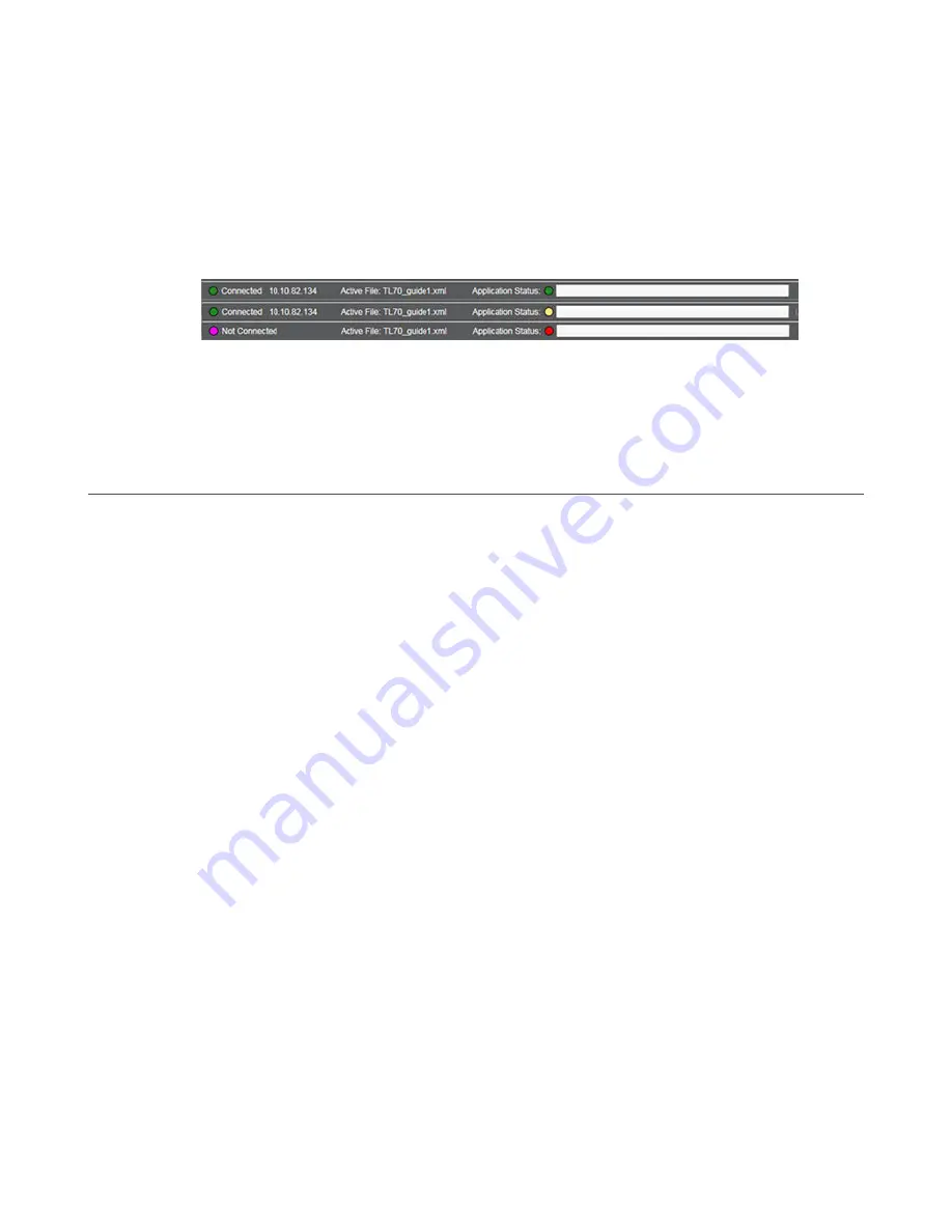
Figure 11. Status indicator bar

If the Application Status indicator is red, close and restart the DXM Configuration Tool, unplug and re-plug in the

cable and reconnect the DXM to the software.

If the Application Status indicator is green, the file upload is complete.

If the Application Status indicator is yellow, the file transfer is in progress.

The device reboots and begins running the new configuration.

4.3 DXM100-A2 Models Only

4.3.1 Binding and Conducting a Site Survey with the ISM Radio

Before the ISM radio can communicate, the ISM radio within the DXM must be bound to the other radios in the wireless

network.
Use the DXM LCD menu to bind external radios to the internal ISM radio.
If you are having difficulty running binding or site surveys, it may be because of the speed of the XML configuration file or

script running on the DXM. To resolve this issue, try one of the following options:

Disable the XML and script by setting DIP switch 4 on the processor board to ON and cycling the power to the DXM.

After binding the devices, turn DIP switch 4 back OFF and cycle power again to return to normal operation of the XML

and script.

Adjust the XML or script to slow down the RTU read or write rules.

Upload a blank XML, bind all devices, then upload the configured XML file.

4.3.2 Bind a DX80 Node to a DXM and Assign the Node Address

Binding Nodes to a Gateway ensures the Nodes only exchange data with the Gateway they are bound to. After a Gateway

enters binding mode, the Gateway automatically generates and transmits a unique extended addressing (XADR), or binding,

code to all Nodes within range that are also in binding mode. The extended addressing (binding) code defines the network,

and all radios within a network must use the same code.

1. Apply power to all the devices.

Separate radios by two meters when running the binding procedure. Put only one DXM Gateway into binding mode at
a time to prevent binding to the wrong Gateway.

2. Enter binding mode on the DXM radio:

a) Use the arrow keys to select the 

ISM Radio

 menu on the LCD and press 

ENTER

.

b) Highlight the 

Binding

 menu and press 

ENTER

.

3. Assign the Node address to the Node.

For Nodes without rotary dials: Use the DXM arrow keys to select the Node address to assign to the DX80 Node

about to enter binding mode. The DXM assigns this Node address to the next Node that enters binding mode.

Only bind one Node at a time.

For Nodes with rotary dials: Use the Node's rotary dials to assign a valid decimal Node Address (between 01 and

47). The left rotary dial represents the tens digit (0 through 4) and the right dial represents the ones digit (0

through 9) of the Node Address. You can leave the DXM "Bind to" address set to 1 because the Node's rotary

dials will override that setting.

4. Start binding mode on the DXM radio by pressing 

ENTER

 on the DXM radio.

5. Enter binding mode on the DX80 Node.

For housed radios, triple-click button 2.


DXM Enclosure Kit (DEK) Series


www.bannerengineering.com - Tel: + 1 888 373 6767

13

Summary of Contents for DXM Series

Page 1: ...DXM Enclosure Kit DEK Series Instruction Manual Original Instructions 223953 Rev A 20 July 2021 Banner Engineering Corp All rights reserved 223953...

Page 2: ...Node to a DXM and Assign the Node Address 13 4 3 3 Conduct a Site Survey from the DXM 14 5 Activating Services 15 5 1 Banner Cellular Data Services 15 5 1 1 Activate Cell Services 15 5 1 2 Create an...

Page 3: ...ations typically isolated from traditional infrastructure A five watt solar panel delivers a nominal 12 V DC standard output built with a heavy duty anodized frame and rugged design for withstanding h...

Page 4: ...ord grips into locations 3 and 4 4 Install the smallest cable gland PG7 for the solar cable at location 2 2 2 Wire the Battery The battery and DXM ship from the factory pre mounted to the DIN rail 1 I...

Page 5: ...g cleat with the arc facing out Convex orientation b Leave the hardware a little loose so that the bracket can slide onto the panel frame between the mating surfaces c Move the cleat to the center of...

Page 6: ...p until it clicks closed 3 Wire the solar panel to the DXM Figure 5 Solar panel wiring to the DXM a Feed the cable from the solar panel to the DXM through the small cable gland b Connect the brown lea...

Page 7: ...eraging trending and thresholding Low complexity solutions SMS text message Notifications Email Notifications Push data on conditions Text Programming Language ScriptBasic Medium complexity solutions...

Page 8: ...1 1 1 1 1 1 LED2 TB1 C6 R82 TB4 P2 P4 SW1 C4 P5 SW2 P10 TB3 P7 TB2 TB9 Y1 P6 L2 TB5 TVS1 L1 R77 P9 P8 P1 LED1 P3 A B C D G H J K L 1 18 19 32 M L Pin Name Description 1 No Connection Not used 2 PW 12...

Page 9: ...registers 503 1A maximum at 30 V DC 24 N2 NMOS OUT 2 NMOS switch to ground controlled by I O Modbus registers 502 1A maximum at 30 V DC 25 N1 NMOS OUT 1 NMOS switch to ground controlled by I O Modbus...

Page 10: ...minute intervals Two DC latching outputs toggling every 5 minutes One temperature humidity probe powered from 16 V switched power reading every 5 minutes ScriptBasic program controlling temperature h...

Page 11: ...isters Local Registers in Use screen The bottom status bar displays the communications status application status and the DXM Configuration Software version In this short example we will configure the...

Page 12: ...e to display the parameters 3 Name your rule 4 Select the slave ID 5 Select how many registers to read and the beginning register 6 Define the register type how often to read the register and any othe...

Page 13: ...P switch 4 back OFF and cycle power again to return to normal operation of the XML and script Adjust the XML or script to slow down the RTU read or write rules Upload a blank XML bind all devices then...

Page 14: ...site survey on a DX80 network does not affect the throughput of the DX80 network The DX80 Gateway Node system can run a site survey analysis while the network is operational For a MulitHop network the...

Page 15: ...ellular data opening screen 3 Select the region the system is operating in If the system is within the contiguous United States select United States from the region drop down list If the system will b...

Page 16: ...ed to the cellular network 5 2 Banner Cloud Data Services BannerCDS 5 2 1 Activate Cloud Services Follow these instructions to activate your cloud services account 1 Go to the bannercds com website 2...

Page 17: ...nner Cloud Data Services website 3 Verify the Server Name IP is set to push bannercds com and the Page is set to push aspx for sending to the website 4 Set the Cloud Push Interval to a value appropria...

Page 18: ...esent your specific kit After the XML file is loaded into the webserver the webserver uses the register names and configurations defined in the configuration file 5 Click on the Site Name link to go t...

Page 19: ...d from the enclosure 6 Use the included screws to fasten the plate to the enclosure Do not over torque 7 Use the 2 13 16 to 3 3 4 pole clamps and the geometry of the plate tabs to fasten the enclosure...

Page 20: ...ensure no ground loops are created No surge suppressor can absorb all lightning strikes do not touch the Sure Cross device or any equipment connected to the Sure Cross device during a thunderstorm Ex...

Page 21: ...ANTY IS EXCLUSIVE AND IN LIEU OF ALL OTHER WARRANTIES WHETHER EXPRESS OR IMPLIED INCLUDING WITHOUT LIMITATION ANY WARRANTY OF MERCHANTABILITY OR FITNESS FOR A PARTICULAR PURPOSE AND WHETHER ARISING UN...

Page 22: ...modify 17 save 13 upload 13 upload to website 18 configure cloud settings 17 create new site 16 M modify configuration file 17 multiple registers 11 registers 17 R registers multiple registers 11 S sa...

Reviews: