2 Controller Enclosure
The DEK100 Series kit includes an enclosure assembly with the following parts already installed.
•
DXM Controller with USB programming cable
•
Lithium-Iron Phosphate (LiFePO
4
) battery with flying leads
•
LTE tape antenna threaded to the second SMA connector for the cellular module (on all models)
•
Multi-band tape antenna threaded to the ANT SMA connector for the ISM radio (only on A2 model)
•
DIN rail with four end clamps to securely position the DXM Controller and battery
To complete the assembly:
1. Install a set of cord grips to secure the solar cable.
2. Wire the inputs to the Controller.
3. Install the vent to exhaust excessive heat.
4. Wire the battery to the appropriate terminals to supply power to the Controller.
2.1 Install the Cord Grips
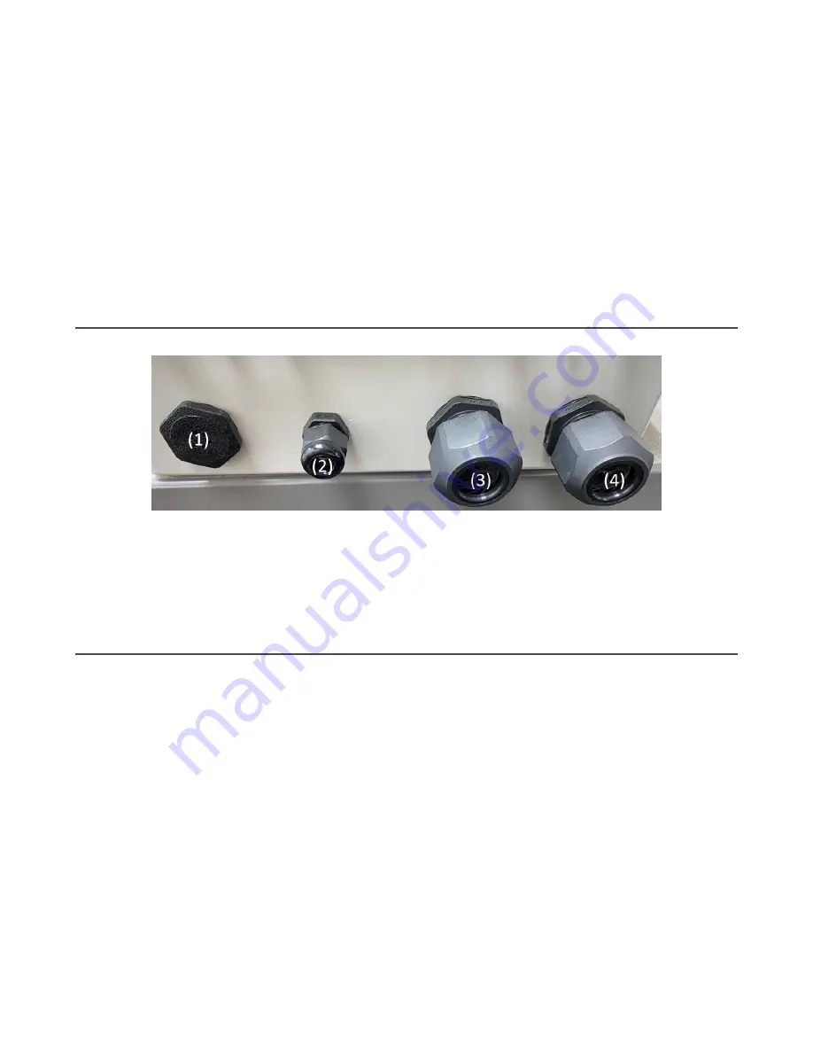
Figure 1. Cord grip placement
1. Open the accessory bag of cord grips and install them in the pre-drilled holes in the bottom of the enclosure.
Tighten the cord grips carefully to avoid stripping the nut across the threads.
2. Place the vent below the battery to ensure proper ventilation (1).
3. Insert the three-cable cord grips into locations (3) and (4).
4. Install the smallest cable gland (PG7) for the solar cable at location (2).
2.2 Wire the Battery
The battery and DXM ship from the factory pre-mounted to the DIN rail.
1. If necessary, remove the DXM from the DIN rail to provide better access to the wiring terminals. To remove the DXM:
a) insert a small flat blade screwdriver in tab shown (1) and pry the spring-loaded DIN rail catch outwards. The catch
releases the bottom part of the DXM.
b) Rock the bottom of the DXM up, then slide the DXM up and off the top part of the DIN rail.
c) Verify the antenna connection(s) remain fastened to the DXM. Note that the antenna connected to the ANT
terminal will only be available in the DEK100-A2 model.
2. On the battery's black (0 V DC) wire, cut approximately one inch off (just behind the tape cap on the end) and then
strip the wire sheathing back 0.25 inches.
3. Connect the black lead to the GD terminal on the bottom of the DXM.
4. Verify the antenna(s) are still fastened to the DXM. Supplying power without a connected antenna may damage the
wireless module.
5. Repeat the strip back procedure with the red lead and connect it to the
B+
terminal.
The controller will power up at this time.
DXM Enclosure Kit (DEK) Series
4
www.bannerengineering.com - Tel: + 1 888 373 6767


