background image

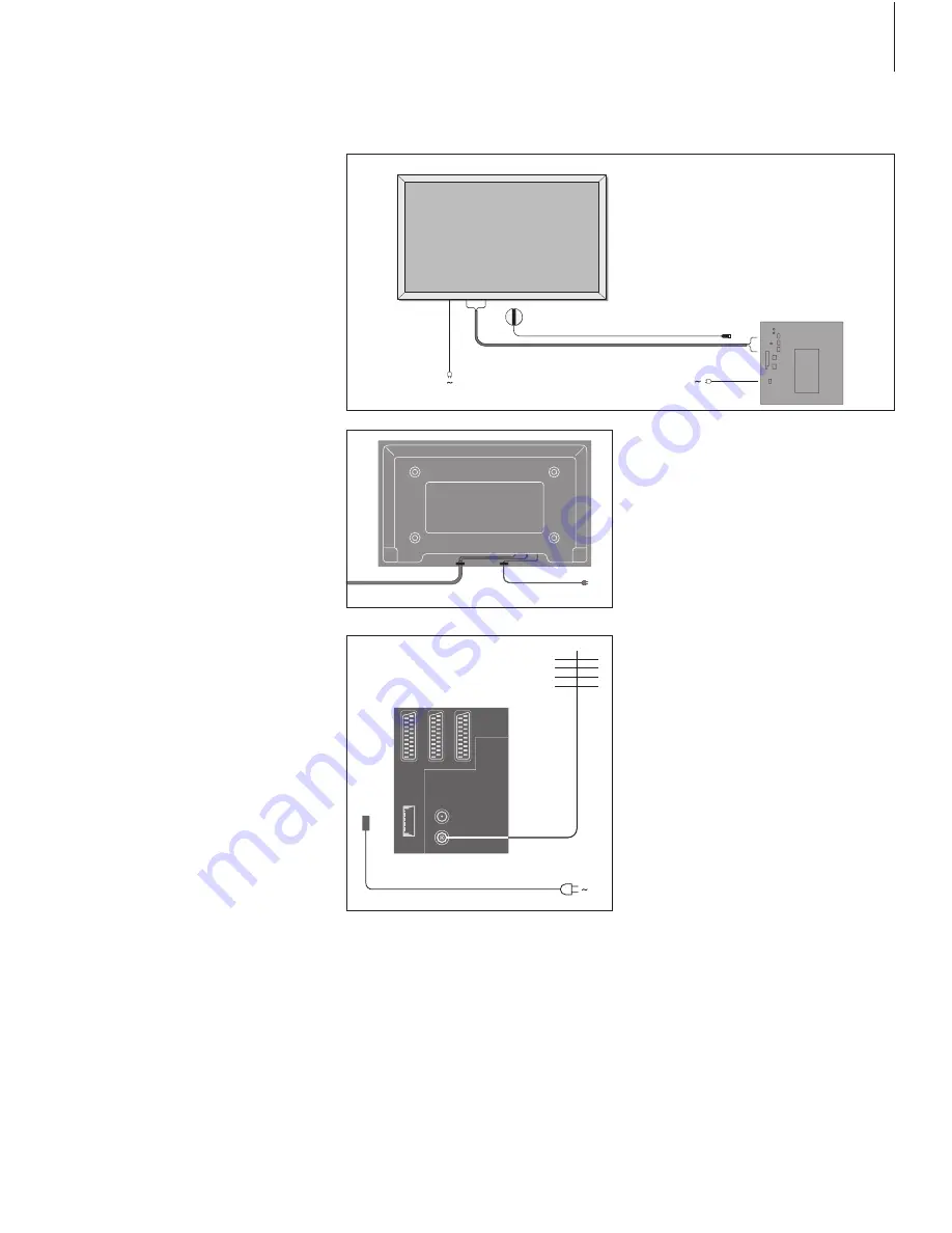
Connect the plasma screen 

If longer cables are necessary, they are 
available from your Bang & Olufsen retailer. 

The two plugs at each end of the cable only 

match specific sockets, so it is not possible to 
connect the cables incorrectly if you follow 
the procedure described below:

–  Connect one 15-pin plug to the RGB socket on 

BeoSystem 2 and the 9-pin plug at the same 
end to the RS232 socket on BeoSystem 2. 

–  Connect the 15-pin plug at the opposite end to 

the PC IN socket on the screen, and the 9-pin 
plug at the same end to the SERIAL socket on 
the screen. 

–  Connect the IR receiver to the appropriate IR-IN 

socket on BeoSystem 2. 

–  Connect the two mains cords to the appropriate 

sockets on BeoSystem 2 and the screen, but do 
not connect them to the mains yet! 

Aerial and mains connection 

Make sure that BeoSystem 2 and the screen 
are placed properly before connecting the 
system. 

> Connect the screen to the mains. 
> Connect the aerial to the socket marked VHF/

UHF on BeoSystem 2. 

> Connect BeoSystem 2 to the mains. 

If you have not yet connected speakers, or you 
wish to connect any other equipment to 
BeoSystem 2, do not connect to the mains yet! 

When connections are complete…

Switch on the mains switch on the back of 

BeoSystem 2. The system is in standby mode and 
ready to be used. You can now begin tuning in 
channels, as explained in 

‘Tune in TV channels’

 on 

page 26 in the Guide. 

BeoVision 4 was designed to be left in standby 
mode when not in use. Therefore, to facilitate 
remote control operation, it is essential that you 
leave the mains switch on. 

RGB

RS232

SE

R

IA

L

PC

 IN

IR-IN

*

BeoSystem 2

7

It is necessary to secure the mains cord in the 
cable bands, as shown in the diagram. Otherwise, 
the mains cord can be tugged free of the socket. 

Summary of Contents for BeoVision 4

Page 1: ...Reference book BeoVision 4...

Page 2: ...ht be useful if you move your products or expand your system at a later date The Guide and the Reference book both contain an index which can help you find the specific subject you want to know more a...

Page 3: ...connect a set top box decoder High Definition HD source or a PC to BeoSystem 2 and how to register extra equipment Audio system with BeoVision 4 26 Find out how to connect an audio system to BeoSyste...

Page 4: ...F Do not attempt to open your products Leave such operations to quali ed service personnel BeoSystem 2 Place BeoSystem 2 in the Cabinet If you do not wish to use the Cabinet make sure that there is s...

Page 5: ...et panel 7 AV and aerial socket panel 8 Fan socket The plasma screen 1 Speaker connection panels 2 A V connection panel 3 Mains connection When connecting external loudspeakers connect them to the lou...

Page 6: ...ends the appropriate control signals to your plasma screen or other connected equipment When mounting the IR receiver make sure to place the receiver on the same wall as the screen If the IR receiver...

Page 7: ...and mains connection Make sure that BeoSystem 2 and the screen are placed properly before connecting the system Connect the screen to the mains Connect the aerial to the socket marked VHF UHF on BeoSy...

Page 8: ...mage to remain on the screen Examples of still pictures are logos video games computer images and images displayed in 4 3 picture format Cleaning the Beo4 remote control Wipe the Beo4 remote control w...

Page 9: ...ket provides the opportunity to connect either an AV decoder or an RF decoder The socket may be used for an AV 2 Expander instead which gives the opportunity to connect a decoder or other non Bang Olu...

Page 10: ...or connection of for example a DVD player SPDIF 2 is for digital input from equipment connected to the V TAPE socket on BeoSystem 2 If the V TAPE socket is set up for V Mem or None the SPDIF 2 socket...

Page 11: ...The Service menu appears Press 1 to bring up the Monitor menu Press p to highlight Plasma version setup and press GO Press m or p to select the screen type and press GO to store it Press EXIT to leave...

Page 12: ...rder BeoSystem 2 automatically registers the signal and you can see the pictures from the Camcorder on BeoVision 4 If the signal from the Camcorder is switched off Press LIST repeatedly to display CAM...

Page 13: ...e three illustrations to the right show examples of BeoVision 4 and speakers placed in various types and sizes of rooms The following guidelines apply for all speaker setups Always use your most power...

Page 14: ...ont and rear sets of speakers to L or R left and right channel to indicate their position in each speaker set Set the left front speaker to L the right rear speaker to R and so on If you have only one...

Page 15: ...and press m or p to select the distance in metres between your viewing position and each of the speakers When you have entered the speaker distances press GO to store your settings or press EXIT to le...

Page 16: ...d when your speaker calibration is complete refer to the chapter Adjust picture and sound settings on page 35 in the Guide The sound level from the centre speakers functions as your point of compariso...

Page 17: ...in menu Press 3 to bring up the Setup menu Press 2 to bring up the Sound menu Press 5 to bring up the Speaker mode menu Press or to switch between speaker modes and or to move between Video and Audio...

Page 18: ...R on BeoSystem 2 Remote control operation of equipment connected via the AV 2 Expander is not possible Video recorder Use a 21 pin cable to connect a Bang Olufsen video recorder to the V TAPE socket o...

Page 19: ...p box do not cover its IR receiver entirely If you connect two set top boxes You will need an IR Y adaptor index number 6174171 to connect two set top boxes to BeoSystem 2 Please contact your Bang Olu...

Page 20: ...top box you will be asked to select your set top box type from an on screen list For further information refer to the chapter Register and use additional video equipment on page 32 in the Guide When y...

Page 21: ...the external aerial cable to the decoder input socket and then forward the cable to the BeoSystem 2 aerial socket marked VHF UHF Connect the RF decoder to the 21 pin socket marked DECODER on BeoSyste...

Page 22: ...eoSystem 2 is for connection of a HD source such as a set top box or a PC Examples of possible setups are shown below VGA IN DECODER V TAPE AV SPDIF1 L R VIDEO DVI PC V MEM DVD HD STB BeoSystem 2 BeoV...

Page 23: ...VGA IN socket on BeoSystem 2 Camera STB DTV DVI STB AUX DVI for a set top box connected to the DVI socket on BeoVision 4 PC DVI for a PC connected to the DVI socket on BeoVision 4 Get access to HD sou...

Page 24: ...your HD source is on Press LIST repeatedly until FORMAT is shown Press to be able to adjust the picture Press to move the picture up or down Press to move the picture left or right Press to decrease p...

Page 25: ...25...

Page 26: ...em you may need to set it to the correct Option Option setting is done with the Beo4 remote control and with the entire system switched to standby Option setting for BeoVision 4 While holding down the...

Page 27: ...ST AV TV LIST AV CD 27 To listen to sound from a television source on your audio system speakers without switching on the screen press LIST repeatedly to display AV on Beo4 and then press a source but...

Page 28: ...Under certain circumstances it may be necessary to enter modulator settings Link connections The main room system must be connected to the link room system with a Master Link cable Connect the Master...

Page 29: ...enus without storing Link frequency If for example a TV channel in your area is broadcasted on the same frequency as the BeoLink system uses 599 MHz you must tune the system modulator to an unoccupied...

Page 30: ...room must be connected to your main room system using two different cables BeoLink connection using a Master Link cable and a junction box Aerial connection using an ordinary aerial cable BeoLink con...

Page 31: ...the system in the main room and the Timer function must be activated on the BeoVision 4 For more information refer to the chapter Make BeoVision 4 start and stop automatically on page 18 in the Guide...

Page 32: ...old the standby button down Press to get access to the Beo4 setup function Let go of both buttons ADD appears in the display Press repeatedly to display CONFIG on Beo4 Press to be able to select the t...

Page 33: ...n the list MOVED appears indicating that the button has been moved You leave the Beo4 setup function automatically Press and hold the standby button down Press to get access to the Beo4 setup function...

Page 34: ...adjustment options Timer play TV list Setup Tuning Sound Picture Connections Menu Clock V Mem Adjustment Speaker type Speaker distance Speaker level Speaker mode Sound system Edit TV list Add program...

Page 35: ...Start and stop times Key in the times when you want the system to start and or stop playing If you have chosen Standby as your source then enter only the stop time Date or Days Fill in the date you w...

Page 36: ...it tuned TV channels on page 28 in the Guide What s on the Add program menu Freq frequency Shows the frequency during the Add program process Pr program number Shows the program number during the Add...

Page 37: ...s connected to BeoSystem 2 you can choose between Dec1 Dec2 or Off Sound mono stereo language Several types of sound may be available for a TV channel Examples can be stereo sound mono sound or other...

Page 38: ...e in metres between your viewing position and BeoVision 4 What s on the Speaker level menu Front Adjust the sound level from your left and right front speakers Rear Adjust the sound level from your le...

Page 39: ...a speaker mode for video sources Options are Speaker 3 The centre speakers front speakers and the BeoLab 2 subwoofer are active Speaker 5 Surround sound from all speakers including the BeoLab 2 subwoo...

Page 40: ...steps of two within a range of 00 to 62 32 is the neutral setting Colour Colour intensity can be adjusted in steps of two within a range of 00 to 62 32 is the neutral setting Contrast The contrast lev...

Page 41: ...What s on the Clock menu 39 Connections Additional video equipment 18 DVD player AV 2 Expander Video tape recorder Video Game Camcorder etc Aerial and mains connection 7 Audio system connect to BeoSy...

Page 42: ...tance 15 What s on the Speaker distance menu 38 What s on the Speaker level menu 38 What s on the Speaker mode menu 39 What s on the Speaker type menu 38 Maintenance BeoVision 4 8 Changing the Beo4 ba...

Page 43: ...unctions Guide p 12 Go directly to a page via Fastext Guide p 17 Store favourite teletext pages memory pages Guide p 12 Teletext large mix and reveal Guide p 16 Updated teletext pages Guide p 16 Timer...

Page 44: ...www bang olufsen com...

Reviews: