User instructions
51346-007 GB/2020-08
C
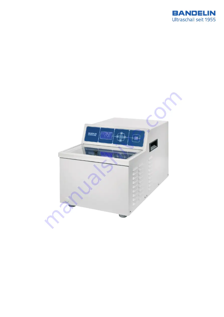
High-performance ultrasonic bath
255
Page 1: ...User instructions 51346 007GB 2020 08 C High performance ultrasonic bath C 255...
Page 2: ...is document the original version has priority BANDELIN accepts no responsibility or liability for damages caused by improper handling or usage contrary to the intended purpose The documentation was pr...
Page 3: ...onformity will expire If Service is required please contact the specialist dealer in charge or the manufacturer Symbols used Symbol Significance Explanation Danger Identifies information that could si...
Page 4: ...14 2 1 Scope of delivery 14 2 2 Set up assembly 14 2 3 Start up 15 3 Operation 16 3 1 Operating elements 16 3 1 1 Turning the ultrasonic bath on o 16 3 1 2 Explanation of the display fields 17 3 2 Si...
Page 5: ...Maintenance and repair 30 6 1 Maintenance 30 6 2 Maintenance conducted by the manufacturer every 2 years 34 6 3 Malfunction Fault analysis 34 6 3 1 Fault messages on the display 35 6 3 2 Malfunctions...
Page 6: ...t features Stainless steel oscillating tank 1 with transducers ultrasound frequency 35 kHz Filling level mark for safe filling 2 electronic fill level sensor 2a Operating and display panel 3 with LC d...
Page 7: ...51346 007 GB 2020 08 7 46 1 electronic GmbH Co KG Heinrichstra e 3 4 12207 Berlin Deutschland info bandelin com 12 10 8 11 2 2a 7 6 1...
Page 8: ...ures Cooling is conducted automatically the ultrasound can be separately switched on In addition to the temperature the runtime can be set for up to 99 59 59 hours In addition four di erent levels of...
Page 9: ...5 litres contact liquid 4 litres in the tank 1 litre in the cooling unit Adjustable bath temperature 4 40 C in 20 C environment Cooling capacity 200 W HF power 180 W adjustable to 4 levels HF frequenc...
Page 10: ...al number year of manufacture See type plate for information The ultrasonic bath has been inspected according to applicable standards and must be installed and operated according to EMC directions see...
Page 11: ...control e g using an CLP SubD pin Name of signal ML pin Remark 1 PE 1 Ground potential connected to GND 2 TxD 1 3 SCI TxD 3 RxD 1 5 SCI RxD 4 7 Not connected 5 GND 9 Combined ground potential for all...
Page 12: ...ath directly to sunlight and do not position it in the vicinity of heat sources Keep the surface of the ultrasonic bath and operating elements clean and dry Do not expose the ultrasonic bath to corrod...
Page 13: ...ok The cooling circuit may not be damaged If the cooling circuit is damaged immediately disconnect the power plug and ventilate the installation room well Send the ultrasonic bath for repair to the ma...
Page 14: ...cluding 1 beaker holder PH 255 11 1 lid D 255 G 20 inset beakers SD 01 2 1 drain hose 1 mains cable 2 rubber stoppers as transport safety devices 1 TICKOPUR TR 3 250 ml 1 Instruction manual Additional...
Page 15: ...be removed with a suitable cleanser before first use see Chapter 5 Connect the ultrasonic bath up to the power supply grounded socket To conduct a function test fill and ventilate the oscillating tank...
Page 16: ...ter turning on the LC display must light up Initialisation occurs automatically BANDELIN electronic S O N O C O O L initialising Next the ultrasonic bath will be on stand by mode and will be ready for...
Page 17: ...perature in the oscillating tank in C Target runtime Specified value for the duration of the ultrasound operation in hh mm ss format Note As soon as the ultrasonic bath is turned on the cooling will r...
Page 18: ...parameter and the current value are shown on the top portion of the display All valid target values are shown on the bottom rows Stand by mode SET key Active mode SET key Pause mode SET key Active mod...
Page 19: ...time in editing mode Setting limits 4 40 C Notes If the actual temperature exceeds the value of the target temperature by more than 0 7 C the ultrasonic bath will shut o the ultrasound for safety reas...
Page 20: ...remaining runtime can be edited This setting however will not change the runtime specification saved value in stand by mode Setting limits 00 00 10 99 59 59 hh mm ss 3 4 3 Power setting The power can...
Page 21: ...e by pressing the START STOP key once again in pause mode By pressing the SET key for 2 sec the procedure can be interrupted from pause mode and the display values can be reset return to stand by mode...
Page 22: ...in place without fail First fill the oscillating tank approx 1 3 full with water then add 50 ml TICKOPUR TR 3 Next add water up to 2 cm above the filling level mark Power on the ultrasonic bath using...
Page 23: ...nts household cleaners and dish detergents for sonication in the stainless steel tank When working with aggressive preparations in inset beakers or insert tubs Prevent the contact fluid or stainless s...
Page 24: ...from below the vessels When using sample containers e g sample cassettes for decalcification of bone tissue make sure of the following All samples must be fully covered with fluid If sample cassettes...
Page 25: ...ver from the emptying nozzle and slide the supplied drain hose onto the emptying nozzle Place the other end of the drain hose in a suitable recipient or in the sink Insert the rubber stopper in the in...
Page 26: ...days before having to be replaced Note In order to prevent clouding or precipitation of the contact liquid when using very hard water the contact liquid can be mixed with deionised water 4 5 2 E ect...
Page 27: ...parations made by DR H STAMM GmbH are prepared pursuant to the regulations of the German Washing and Cleansing Agents Act are biodegradable and as working solutions may be disposed of in the wastewate...
Page 28: ...trasonic bath see chapter 4 4 Repeat the described rinsing process two to three times After the last emptying wipe dry the oscillating tank using a soft cloth Oscillating tank The oscillating tank of...
Page 29: ...n the rim of the bath and around the outflow which can result in a cross infection Consequently the baths and surfaces of the device must be disinfected and cleaned regularly The disinfection should b...
Page 30: ...ltrasonic bath Open the shut o valve for 1 minute Permanently replenish the liquid to ensure that the fill level sensor is constantly immersed in it Close the shut o valve 3 5 litres of liquid should...
Page 31: ...sponding value in the technical data chapter 1 4 tolerances 20 Switch o the ultrasound once again Turn on the cooling To do so lower the target temperature to more than one degree below the actual tem...
Page 32: ...s important that the test conditions remain constant level of liquid in the oscillating tank 2 3 and in the sample vessel temperature of the tank contents degassing time if applicable degassing for 10...
Page 33: ...nd irradiate the foil for at least one minute until a visible perforation or holes are produced With sturdier foils thicker or coated ones the irradiation time can last up to 3 minutes 7 Switch o the...
Page 34: ...ange of internal components i e hoses if necessary and technical safety controls For information on shipment of the ultrasonic bath see chapter 6 4 6 3 Malfunction Fault analysis SONOREX ultrasonic ba...
Page 35: ...ultrasound cannot be started and or the ultrasonic bath turns o for safety reasons Wait until the cooling has su ciently cooled the contact liquid tolerance range target temperature 0 7 C 012 Error 0...
Page 36: ...ing tank blocked Control the inflow and outflow and rectify the blockage obstruction remove the rubber stoppers in the tank s inlet and outlet see chapter 4 1 If needed the ultrasonic bath must be flu...
Page 37: ...on within the ultrasonic bath In such a case the interior conduit system must be rigorously flushed as follows Remove the outlet s protective cover and connect the drain hose included in the scope of...
Page 38: ...e cleaned and decontaminated if necessary see the following chapter 6 4 1 Decontamination certificate If the ultrasonic bath is sent back to the manufacturer for repairs with accessories if applicable...
Page 39: ...nu with system data e g serial number and software version may be opened With repeated simple pressing of the key a third sub menu will open with the setting data for the HF generator FH1 The Service...
Page 40: ...use of the ultrasound and also protect the oscillating tank and instruments BANDELIN o ers a broad range of accessories Additional information may be obtained from our supplier our sales representati...
Page 41: ...3515 Beaker holder PH 255 1 3519 Beaker holder PH 255 2 3518 Beaker holder PH 255 11 3512 Grommet SCH 255 3520 Inset beaker SD 01 2 Pkg 10 units 3517 Implant box IB 18 Pkg 5 units 3283 Glass beaker S...
Page 42: ...of the reach of children and also of persons who have not been instructed in their use by reference to the product information Do not ingest or inhale the preparations and do not allow them to come in...
Page 43: ...ooling 6 8 13 17 18 23 31 35 Cooling circuit 13 Cooling unit 13 D De airing 22 23 Declaration of Conformity 8 Degree of protection 9 Display LCD 6 16 17 18 21 22 30 35 36 38 Disposal 27 Drain hose 14...
Page 44: ...r 14 Outgoing air opening 6 13 15 31 Outlet 6 12 15 22 25 26 28 36 P Pause mode 18 19 20 21 Power 18 20 31 36 Power setting 20 Power specification 17 Power switch 6 16 22 24 25 36 Preparation 14 36 Pr...
Page 45: ...19 Temperature value 39 TICKOPUR 14 22 26 32 42 Time setting 20 Transportation 12 15 23 25 26 29 Transportation damages14 Transportation safety device 14 Type plate 6 10 Types of operation 18 U Ultra...
Page 46: ...Note The user instructions in this and other languages as well as further information can be found in the enclosed CD...