


www.balluff.com
31
english
Dynamic Teach (Balluff spec.)
This teach process is only available in Two-Point and
Window Mode. As with the previous process, the
measurement values are dynamically recorded over a
defined period of time. Measurement value acquisition is
started via the
Dynamic Teach SP1 Start
system
command, but ended here with
Dynamic Teach SP2 Stop
.
If all recorded measurement values were in the valid
detection range, the switching point calculation is started.
The minimum and maximum values are determined for this
purpose. Unlike the previous process, the maximum value
is used as switching point 1 (SP 1) and the minimum value
as switching point 2 (SP2). The maximum acquisition time
is again 5 minutes. After 5 minutes without a Stop
command, the event 0x8DC0
Teach Timeout
is set.
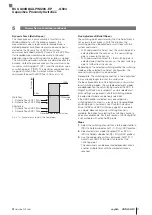
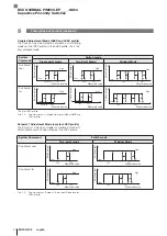
Fig. 5-13:
High
SP1
SP2
Low
Workflow:
1. Dynamic Teach SP1 Start
2. Dynamic Teach SP2 Stop
Alternative:
1. Dynamic Teach SP2 Start
2. Dynamic Teach SP1 Stop
Recorded measurement values
Measured
value
Switch output
Dynamic Teach (Balluff) (Two-Point Mode)
5
Primary Device Functions (continued)
Fine Adjustment (Balluff Spec.)
The switching point adjustment by the Fine Adjustment is
not a classic teach process. With this process, the
switching point can be adjusted in small steps with two
system commands:
– With command
Fine Adjust near
, the switching point is
adjusted towards the sensor, i.e., the new switching
point is closer to the sensor.
– With command
Fine Adjust far
, the switching point is
adjusted away from the sensor, i.e., the new switching
point is further from the sensor.
Depending on the selected switching profile, the switching
mode and the selected Fine Adjust configuration, the
second switching point is also adjusted.
Prerequisite: The switching channel that is to be adjusted
to was already taught to or set to a valid value.
The basic procedure for a Fine Adjustment is very similar
for all switching modes. The available adjustment modes
are dependent on the set switching mode of the SSC. In
Single Point Switch, only setpoint 1 can be selected; all
other settings are ignored. In all other switching modes,
the adjustment mode can be freely selected.
If the AdSS profile is selected, only one setpoint or
switching point is active. As a result, only Coupled Mode
(switching point + hysteresis, see
as a mode. Because only one switching channel is
available, the option for selecting the switching channel is
also not available here. For these reasons, the Config-ISDU
is not available with active AdSS profile.
Steps
1.
Select the switching channel that is to be adjusted to in
ISDU 0x56 (86) subindex 0x01 (1). (Only LSSC profiles.)
2.
Select adjustment mode (Coupled, SP1 or SP2) in
ISDU 0x56(86) subindex 0x02(2). (Only LSSC profiles.)
3.
Use the appropriate system commands (0xB1 (177)
Adjust near, 0xB2 (178) Adjust far) to adjust the
switching point.
The commands can be executed independent of one
another multiple times until the desired distance is
reached.
BCS Q40BBAA-PIM20C-EP _ _ _ -GS04
Capacitive Proximity Switches
Summary of Contents for BCS Q40BBAA-PIM20C-EP-GS04 Series
Page 1: ...BCS Q40BBAA PIM20C EP___ GS04 deutsch Konfigurationsanleitung english Configuration Guide...
Page 2: ...www balluff com...
Page 3: ...BCS Q40BBAA PIM20C EP___ GS04 Konfigurationsanleitung deutsch...
Page 4: ...www balluff com...
Page 87: ...BCS Q40BBAA PIM20C EP___ GS04 Configuration Guide english...
Page 88: ...www balluff com...
Page 171: ......


