


28
english
5.4
Switching Profiles
5.4.1 Description
Sensor principle / evaluation logic
The sensor performs measurement value acquisition as a
continuous signal that is evaluated for switching signal
generation. The measured value is only evaluated if it is
within the valid measuring range. If the measurement value
is outside of this range, the output switches to always
active. For switching sensors, this value is permanently
defined according to the product. The evaluation is based
on the
Transducer Signal
value (PDObjectId 0x0026 (38)).
Switching points are defined by means of setpoints that
can be determined using various teach processes.
Alternatively, the setpoints can also be set directly via
ISDUs, but in compliance with the same prerequisites and
rules that apply to the Teach procedures.
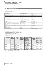
The setpoint setting can also be used to deactivate the
switching point evaluation. This is performed with the
No
Measurement Data
setting:
Status
Value
No Measurement
Data (32 bit)
2,147,483,644 (0x7FFFFFFC)
Tab. 5-5: Switching Profiles – Deactivate switching point evaluation
5
Primary Device Functions (continued)
Overview AdSS – Profile
– Only one switching channel (Switching Signal Channel
(SSC)) available.
– Only one switching point (setpoint) per switching
channel.
– Permanently defined hysteresis according to the
product.
– As switching mode, only the
Single Point Mode
is
available.
– The following teach commands are available:
Single
Value Teach
,
Two Value Teach
and
Dynamic Teach
(profile spec.).
Overview of LSSC – Profile
– Multiple switching channels are possible (up to
4 channels currently supported).
– Two switching points (setpoints) per switching channel.
– Adjustable hysteresis.
– Multiple switching modes are possible:
Single-Point
Mode
,
Two-Point Mode
and
Window Mode
.
– The following teach commands are available for both
setpoint 1 and setpoint 2:
Single Value Teach
,
Two
Value Teach
and
Dynamic Teach
(profile spec. and
Balluff spec.).
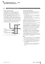
Switchpoint Logic
With switching logic
High Active
, the switching output
switches to high if the current measurement value is
greater than the set (taught) setpoint. With
Low Active
this
logic is inverted.
High Active
Fig. 5-2:
High
SP1
Low
Measured value
Switch output
Switchpoint logic
High Active
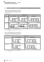
Low Active
Fig. 5-3:
High
SP1
Low
Measured value
Switch output
Switchpoint logic
Low Active
BCS Q40BBAA-PIM20C-EP _ _ _ -GS04
Capacitive Proximity Switches
Summary of Contents for BCS Q40BBAA-PIM20C-EP-GS04 Series
Page 1: ...BCS Q40BBAA PIM20C EP___ GS04 deutsch Konfigurationsanleitung english Configuration Guide...
Page 2: ...www balluff com...
Page 3: ...BCS Q40BBAA PIM20C EP___ GS04 Konfigurationsanleitung deutsch...
Page 4: ...www balluff com...
Page 87: ...BCS Q40BBAA PIM20C EP___ GS04 Configuration Guide english...
Page 88: ...www balluff com...
Page 171: ......


