


Chapter 4. Operation
4.1 Introduction
See
Chapter 2, “Installation”
, and
Chapter 3, “Initial Setup”
,
to prepare your
PanaFlow Z1G/Z2G Process Gas Flowmeter
system for operation. When the meter is ready to take
measurements, proceed with this chapter. The following
specific topics are discussed:
• “Powering Up” below
• “The PanaFlow Z1G/Z2G Process Gas Flowmeter LCD
Display” on page 35
• “The Optional PanaView Display” on page 36
• “Taking Measurements” on page 37
Note:
All inputs and outputs of the PanaFlow Z1G/Z2G
Process Gas Flowmeter are calibrated at the factory prior to
shipment. If it becomes necessary to recalibrate any of the
inputs and/or outputs, consult the factory for instructions.
WARNING!
To ensure the safe operation of the
PanaFlow
Z1G/Z2G Process Gas Flowmeter
, it must
be installed and operated as described in
this manual. In addition, be sure to follow
all applicable local safety codes and
regulations for the installation of electrical
equipment.
4.2 Powering up
Because the
PanaFlow Z1G/Z2G Process Gas Flowmeter
does
not have an ON/OFF switch, it will power up as soon as the
connected power source is energized.
WARNING!
For compliance with the European Union’s
Low Voltage Directive, this unit requires an
external power disconnect device such as
a switch or circuit breaker. The disconnect
device must be marked as such, clearly
visible, directly accessible, and located within
1.8 m (6 ft) of the meter.
There are three methods for obtaining readings from the
PanaFlow Z1G/Z2G Process Gas Flowmeter
:
• Built-in
PanaFlow Z1G/Z2G Process Gas Flowmeter
LCD
display
• PanaView
software installed on a personal computer
• External analog device to read the
PanaFlow Z1G/Z2G
Process Gas Flowmeter
analog output
At least one of the above display options must be installed
in order to obtain flow rate readings from the meter.
Immediately upon power up, the
software version
display
appears. Then, the meter performs a series of internal
checks, which take about 45 seconds, prior to displaying the
flow rate data
(see
“Initial Power On Screens” on page 23
).
Note:
If the PanaFlow Z1G/Z2G Process Gas Flowmeter fails
any of the internal checks, try disconnecting the power and
then re-powering the unit. If the meter continues to fail any
of the internal checks, contact the factory for assistance.
After successfully performing the internal checks, the
PanaFlow Z1G/Z2G Process Gas Flowmeter
begins taking
measurements and the software version display is
replaced by a measurement mode display. Proceed to the
appropriate section for instructions on using the LCD display
and the PanaView display option.
Note:
As a minimum, the system and pipe parameters
for each installed channel must be entered before the
PanaFlow Z1G/Z2G Process Gas Flowmeter can display
valid data. Refer to Chapter 3, “Initial Setup”, for specific
instructions.
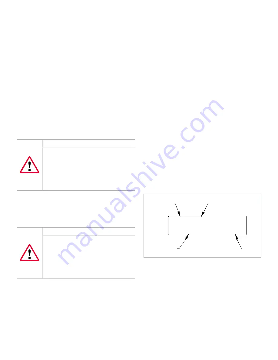
4.3 The PanaFlow Z1G/Z2G process
gas flowmeter LCD display
The components of the
PanaFlow Z1G/Z2G Process Gas
Flowmeter
LCD display are shown in
Figure 17
below, along
with a typical mass flow rate readout.
VEL
Ch1 MDOT
0.00
LB/SEC
Parameter
Channel #
Units
Flow Rate
Figure 17: A typical LCD flow rate display
As shown in
Figure 17
above, the
PanaFlow Z1G/Z2G Process
Gas Flowmeter
display screen includes the following
information:
• Channel Number
• Flow Parameter
• Units of Measure
• Flow Rate Value
However, the items in this list may be reprogrammed to
display a variety of alternative choices (see
“Programming
the LCD Display” on page 37
).
23
Summary of Contents for PanaFlow Z1G
Page 1: ...PanaFlow Z1G Z2G User s manual 910 321 Rev A...
Page 2: ...ii...
Page 4: ...no content intended for this page iv...
Page 9: ...no content intended for this page 1...
Page 21: ...Figure 12 Remote mount electronics transducer and preamplifier wiring ref dwg 702 731 732 13...
Page 28: ...no content intended for this page 20...
Page 30: ...no content intended for this page 22...
Page 38: ...no content intended for this page 30...
Page 40: ...no content intended for this page 32...
Page 43: ...Table 13 Service record cont Date Description of service Performed by 35...


