Consolidated 1900/P Series Safety Valves Instruction Manual
| 23
© 2020 Baker Hughes Company. All rights reserved.
XV. Reassembly of 1900/P Series Safety Valves
Notes:
A. Check all gaskets used during reassembly. Undamaged
solid metal gaskets (not pitted or creased) can be reused.
All soft gaskets must be replaced. Before placing the
(flat) gaskets, apply a light uniform coating of lubricant
to the surface to be gasketed; then coat the top of the
gasket with lubricant.
B. Before reassembling the valve, all parts should be
cleaned. Special attention should be given to guiding
surfaces, bearing surfaces, flange faces, retainer
recesses and grooves.
C. If grinding in of bearing parts is required, use Clover
®
Grade 3A (see Section XV, “Inspection”), and be sure
to remove all grinding compounds and thoroughly clean
both surfaces and rinse with alcohol or other suitable
cleaner.
D.
On D and E valves, be sure to measure the required lift
before final assembly. See Section XVII for instructions.
E.
The final step before final assembly is lubrication Apply
lubricants sparingly, but be sure that each bearing
surface is lightly by uniformly covered. For lubricant see
“Maintenance Tools and Supplies” on Section XX.
A. Reassembly of the valve
1. If the nozzle was removed, apply lubricant to the nozzle
threads before reinstalling the nozzle into the base,
then tighten.
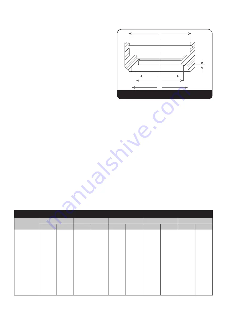
2. Reinstall the adjusting ring to the nozzle. Make sure
the ring is low enough on the nozzle to allow sufficient
clearance between the disc holder and the adjusting
ring so that the disc will seat on the nozzle and not on
the ring (see Figure
21 & Table
5).
3. a) On D and E valves, if the nozzle does not require
any machining, the same limit washer (tagged during
disassembly) may be used again. However, lift
should be checked and verified correct as described
on Section XVI.B.
b) If D or E valve nozzle was remachined, measure the
required lift before final assembly.(Section XVI.B.)
4. Assemble disc, holder ring and disc holder. Use care to
avoid seat damage during assembly. Insert retainer ring
bevelled side upwards in groove using proper inside
snap ring pliers (Figure
29).
5. On bellows valves (see Figure
11), place a new bellows
gasket on the disc holder. Thread the bellows down to
the gasket finger tight on the disc holder. Using a pin
spanner wrench or special cable type wrench, turn the
bellows ring down until a pressure tight seal is obtained.
6. On D and E restricted lift valves, install the limit washer.
7. Place the guide over the disc holder. DO NOT DROP.
If bellows is present, the weight of the guide will slightly
compress the bellows.
E
A
B
C
D
Table 5: Ring Holder Critical Dimensions
Orifice
A max.
B max.
C max.
D max.
E max.
in.
mm
in.
mm
in.
mm
in.
mm
in.
mm
D, E, F
1.814
46.08
1.057
26.85
1.225
31.12
1.484
37.69
.065
1.65
G
1.814
46.08
1.188
30.18
1.327
33.71
1.703
43.26
.070
1.78
H
2.064
52.43
1.358
34.49
1.610
40.89
1.922
48.82
.075
1.91
J
2.502
63.55
1.675
42.55
2.055
52.20
2.516
63.91
.095
2.41
K
2.872
72.95
2.010
51.05
2.455
62.36
3.016
76.61
.095
2.41
L
3.253
82.63
2.435
61.85
3.055
77.60
3.734
94.84
.095
2.41
M
3.753
95.33
2.725
69.22
3.438
87.33
4.266
108.36
.105
2.67
N
3.753
95.33
2.961
75.21
3.760
95.50
4.641
117.88
.105
2.67
P
4.628
117.55
3.552
90.22
4.560
115.82
5.641
143.28
.105
2.67
Q
5.753
146.13
4.562
115.87
5.995
152.27
7.391
187.73
.105
2.67
R
6.628
168.35
5.382
136.70
7.115
180.72
8.766
222.66
.105
2.67
T
8.003
203.28
6.566
166.78
9.220
234.19
10.766
273.46
.105
2.67
Figure 21: Ring Holder Critical Dimensions


