16 |
Baker Hughes
© 2020 Baker Hughes Company. All rights reserved.
Vessel C
Expansion Joint
Recommended
Not
Recommended
In closed systems,
avoid piping strains to
pressure relief valve.
*
Attach vent pipe
rigidly to structure.
Do not connect to drip pan
or the discharge piping.
Vent Pipe
Drip Pan
Pan Drain
Elbow Drain
Vessel B
Long Radius
Elbow
*
Cap may be required
for weather protection.
Vessel A
Long Radius
Elbow
(1)
The pressure drop between the source of pressure in the protected equipment and the valve inlet
(1)
should not exceed 3% of the valve set pressure.
Consolidated Safety valves are checked, set and adjusted at
the factory.
Piping (systems) is the responsibility of the user. One source of
information is ANSI B31.1 Power Piping, Appendix II, “Non-
mandatory Rules for the Design of Safety Valve Installations” in
steam service.
Valves in organic fluid vaporizer service require a closed
discharge piping system.
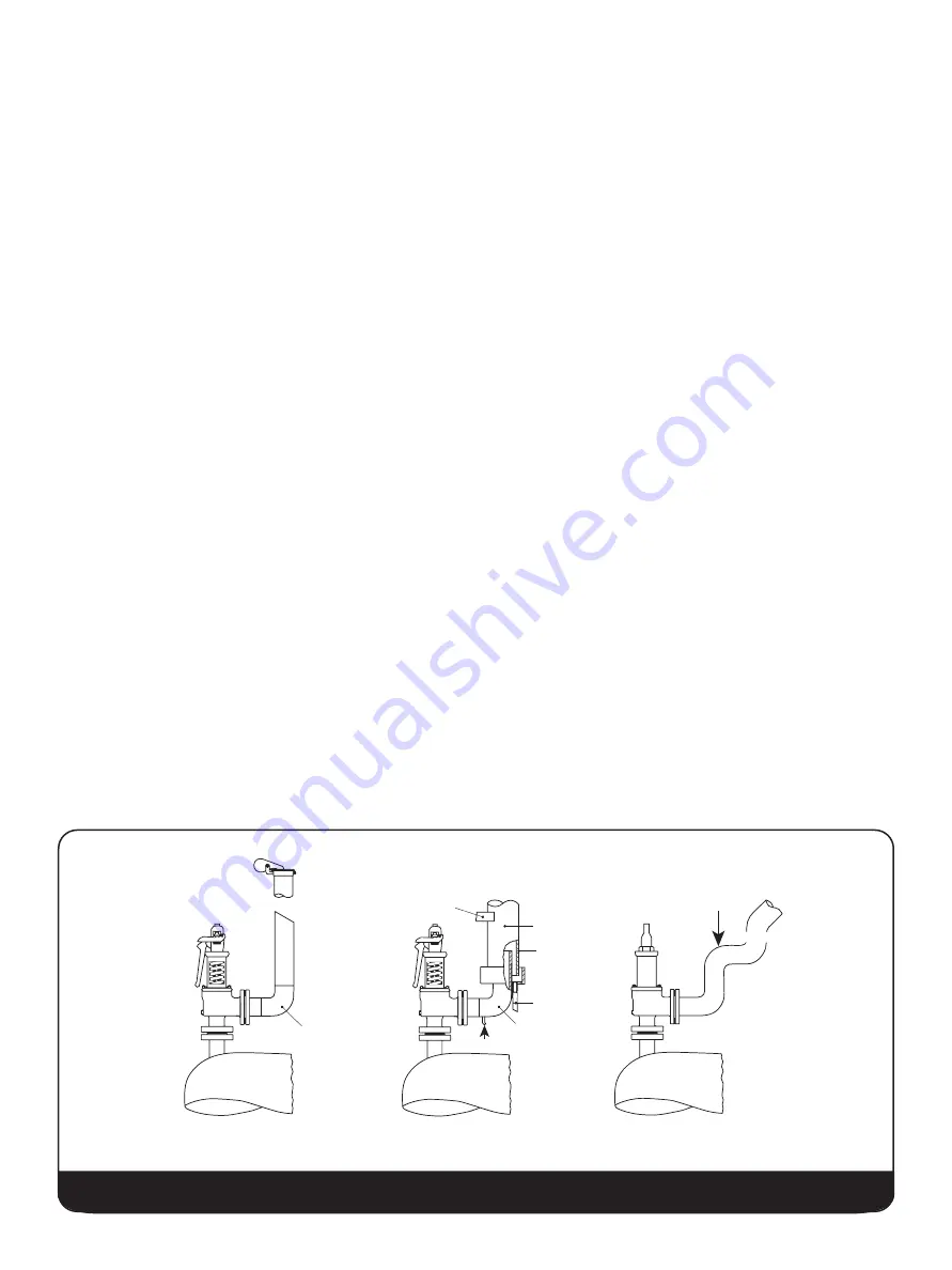
Piping should be as short as possible and in perfect alignment.
Safety valves should be mounted to provide adequate access
360° around the valve plus overhead room to permit removal
for testing and maintenance. A safety valve must never be
installed in any position except the vertical position and
preferably never on the outlet side of an elbow. No stop valve
should be placed between the pressure vessel and its safety
valve except as permitted by applicable Codes. If a stop valve
is located between the pressure vessel and a safety valve, the
stop valve shall have a minimum inside diameter equal to or
greater than the nominal inside diameter of the safety valve
inlet. The inlet piping must be clean before installation.
The discharge piping size must never be less than the valve
outlet size.
For conventional valves, Baker Hughes recommends that the
discharge piping be designed to limit the back pressure to 10
percent of the set pressure. Baker Hughes recommends a
bellows valve (see Consolidated SRV-1 for applicable capacity
factor).
When gags are used in conjunction with setting valves installed
on the boiler, they should be installed after the boiler is at
operating temperature.
When a valve is equipped with a lifting lever, the lever should
be positioned to avoid accidental contact by other equipment or
personnel, which might cause valve to lift accidentally.
Steam service valve body drain must be piped to a safe area. If
left plugged, condensate will collect inside the valve body. If left
open, hot water can escape and present a hazard to personnel
near the valve. Preferably the drain connections (body, elbow
and drip pan) should be piped separately - not main-folded -
because of the tendency of small pipes to plug with rust.
When installing bellows valves, the bonnet vent plug must be
removed and vented (piped) to a safe area.
XI. Recommended Installation Practices
X. General Planning for Maintenance
This manual provides plans for inspection and repair of
Consolidated 1900/P series steam internals safety valves. The
requirements of this manual are considered minimum and do
not relieve the user of the responsibility of applicable codes,
standards and guides, including all safety regulations having
jurisdiction over the installation.
Preventative maintenance should be practiced. At regular
intervals each valve should be removed, disassembled,
inspected, refurbished and tested to the customer’s
requirements.
Figure 9: Installation


