18
18
OPERATION
Safety guard must be properly positioned.
1. Load and secure the piece part to the table.
2. Secure drill or tapping bit in the chuck.
3. Unlock the table, set to desired position, and re-lock.
Adjust the safety guard as necessary.
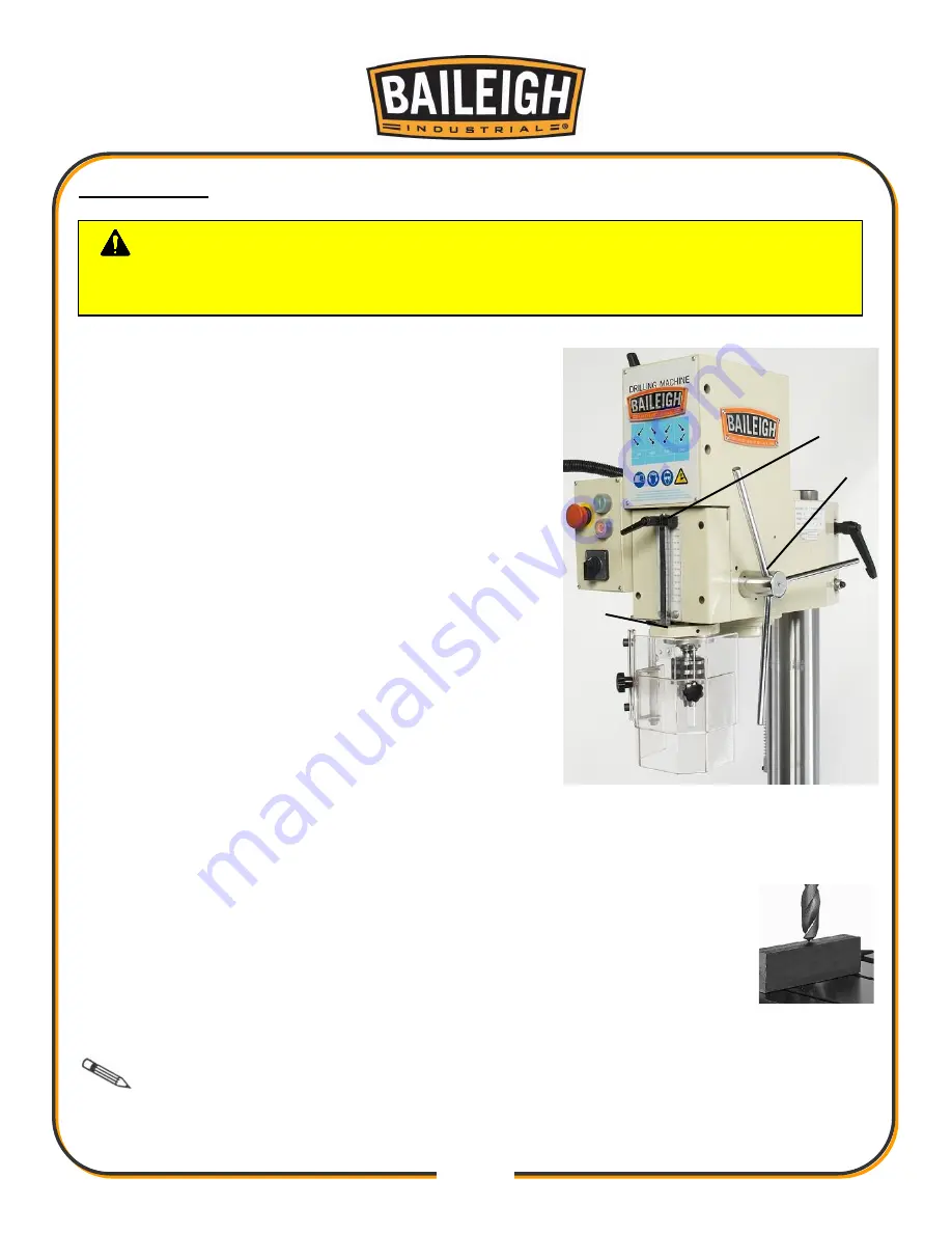
4. To set the depth stop, use the feed handle (O), to
bring the tip of the drill or tapping bit to the surface of
the piece part and hold as in (fig. 2). This is zero
position.
5. While holding the zero position, loosen the depth lock
knob (F) counterclockwise (ccw) to release depth
stop.
6. Lower or raise the depth stop to contact the stop
plate (AA) to set the drill depth. Tighten lock knob (F)
clockwise (cw).
7. Raise the drill or tapping bit off the piece part.
8. Position the spindle speed handles (L) to match the
desired rpm setting as indicated on the speed
selection chart (K).
DO NOT
change spindle RPM
until the spindle has stopped completely.
9. Select either clockwise or counter-clockwise spindle rotation with selector switch (G).
DO
NOT
change rotation direction until the spindle has stopped completely.
10. Verify that the chuck is clear of any entanglements and press start button (J)
to begin spindle rotation.
11. Use the feed handle to start drilling or tapping.
12. While tapping, pause the spindle down-feed at the bottom of the operation to
allow the breaking and reversal of rotation of the spindle.
DO NOT
change
rotation direction until the spindle has stopped completely.
Note: In general, use low speeds for tapping. By tapping at high RPM there is a
danger of damage to the piece part or the tooling. While tapping, the tool can be backed out at
any time by stopping the spindle rotation and changing the selector switch (G).
CAUTION:
Always wear proper eye protection with side shields. Restrain
and contain long hair, loose or baggy clothing and remove jewelry to prevent
entanglement.
figure 2
figure 1
O
F
AA
Summary of Contents for DP-1000G
Page 3: ...Electrical Box Parts List J 38 ELECTRICAL SCHEMATIC 39 ...
Page 15: ...12 12 OVERALL DIMENSIONS ...
Page 16: ...13 13 GETTING TO KNOW YOUR MACHINE F B L N M R G U A P H J C E O D K I S T Q ...
Page 24: ...21 21 DRILL HEAD DIAGRAM A ...
Page 26: ...23 23 GEARBOX DIAGRAM B ...
Page 28: ...25 25 ROTOR SHAFT DIAGRAM C ...
Page 30: ...27 27 2nd SHAFT DIAGRAM D ...
Page 32: ...29 29 3rd SHAFT DIAGRAM E ...
Page 34: ...31 31 COLUMN DIAGRAM F ...
Page 38: ...35 35 SPINDLE SLEEVE DIAGRAM I ...
Page 40: ...37 37 ELECTRIC BOX DIAGRAM J ...
Page 42: ...39 39 ELECTRICAL SCHEMATIC ...


