62
13.4
Output Status Detection
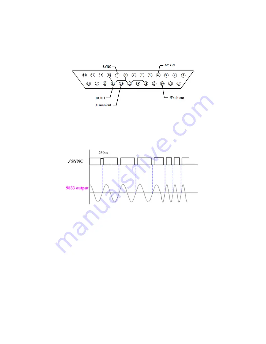
The digital IO interface has system status logic outputs that are described in this section.
All these outputs are in reference to DGND, pins 8, 10, 18, 20, and 22.
Figure 51 - Output status pin out
13.4.1
/SYNC
When the output sine wave of the Instrument is about to pass through 0 degrees, pin 9
(/SYNC) will send out a 250 uS 12 V to 0 V pulse as shown in the below timing diagram.
This output
Figure 52 - Sync Timing Diagram
Summary of Contents for 9830B Series
Page 1: ...1 9830B Series USER MANUAL Model 9832B 9833B High Power Programmable AC Power Sources ...
Page 10: ...ix 2 Notations TEXT Denotes a softkey TEXT Denotes a front panel key ...
Page 28: ...15 6 Menu Tree ...
Page 86: ...73 THD 11 Harmonic 3 weight 21 3 THD 12 Harmonic 3 weight 24 5 ...
Page 88: ...75 THD 15 Harmonic 5 7 weight 2 45 3 95 THD 16 Harmonic 3 5 7 9 weight 11 4 05 2 1 3 ...
Page 89: ...76 THD 17 Harmonic 3 5 9 weight 7 17 3 42 0 8 THD 18 Harmonic 3 5 9 weight 8 11 3 48 1 ...
Page 95: ...82 THD 29 Harmonic 3 5 7 9 11 13 15 weight 33 3 20 13 8 10 8 8 5 7 2 5 5 ...


