26
Chapter 4. Explanation of Operation
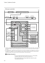
Internal block diagram (interrupted pilot)
An example of wiring for external devices and an internal block diagram are shown
below.
2
3
4
5
6
7
8
10
12
9
11
1
19
20
21
22
23
24
14
15
16
17
L2(N)
L1
Power circuit
K6
K7
K8
Flame output
K5
K1
K2
K3
K4
Alarm output
AUD300C/500C
Flame detector
Shutter
drive circuit
Flame
circuit
Pilot valve 2
Ignition transformer
Pilot valve 1
Main valve 1
Blue
Yellow
White
White
Main valve 2
Burner start
contacts
Prepurge
complete
External
reset input
Emergency stop circuit
Blower on-off circuit / prepurge circuit
Gas pressure
high limit interlock
Gas pressure
low limit interlock
Seismic
limit
Overheating
limit
Air pressure
low limit interlock
*
Input
circuit
10 A
DC24 V
* Air pressure switch: install the following verification circuit.
When the blower is about to start, and there is no air flow, the circuit should verify that no pressure is detected.
If pressure is detected under these conditions, the blower should not be started.
Note
•
According to JIS B 8415, the pilot burner ignition time should be no more than
10 seconds and the main burner ignition time should be no more than 5 seconds.


