25
Chapter 4. Explanation of Operation
CAUTION
This device does not start operation until about 8 seconds after power-on.
After lockout is canceled, start input is not accepted for about 5 seconds.
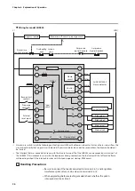
Instrumentation example of model AUR455 for an interrupted pilot
TIC
TIA
PS
PS
PS
Limit/interlock
Burner controller
(AUR455)
IG
Overheating limit
Controller
Combustion
chamber
T/C
T/C
H
UV
L
L
MV1 MV2
PV1 PV2
Ignition
transformer
Gas pressure
upper limit interlock
Gas pressure
lower limit interlock
Combustion
equipment
Seismic limit
Seismic part
Exhaust gas
Exhaust damper
interlock
Flame detector
Flue
Gas
Air pressure
ow interlock
Air
Notes about the instrumentation and circuit configuration for an interrupted pilot
In instrumentation and circuit configuration of the AUR455 for an interrupted
pilot, note the following:
• For safety control and operation circuitry, implement inherent safety design
measures based on risk assessment.
• Directly connect the interlock (including limit) contacts to the interlock input
(terminal 19 or 20 with terminal 22) of the burner controller or configure the
contacts to directly turn off the load (such as the ignition transformer, pilot safety
shutoff valve, or main safety shutoff valve).
• Design a circuit that stops all the burners if the pilot or main burner fails to ignite
or a flame failure occurs.
• Place all the shutoff contacts on the high voltage side of the power supply.
• Take countermeasures against a ground fault as needed, for example by using an
earth leakage breaker or having both contacts cut off.
• Do not provide instrumentation to stop the power to the device as soon as the
alarm output operates. In that case, error history data cannot be guaranteed.


