background image

CORNER DOVETAIL REBATES

19

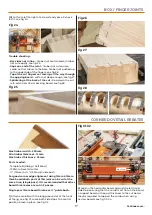
Fig 27-28

Fig 29-30

Fig 23-24

Fig21-22

Fig 25-26

A corner dovetail rebate joint can be achieved in any 

board thickness above 12mm in 2 passes using the ¾” 

guide bush & dovetail cutter -

NB

 - The cutter will need to be loaded in through the 

base of the router with the ⅝" guide bush already in 

position, 19-20. 

DO NOT RELEASE THE PLUNGE FULLY 

WHEN CUTTER IS FITTED

, the cutter will be damaged

as it passes through the inner guide bush.

1)

 Attach comb B with the long groove slot at the front 

of the jig, see fig 21 move both side stops to a central 

position & lock in place, see fig 22.

3)

 Use the wider part of the set gauge to position board 

edge to the centre of the comb slot, see fig 25-26.

Fig 19-20

Side Stop

Side Stop

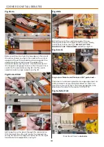
2)

 Mark a line ⅔ thickness of the board, see fig 23 & load 

in the horizontal board. Support board gainst the left 

hand side stop ensuring that the comb is sat flat on the 

board, a support board with equal thickness  to the cut 

board may be required to support the comb when using 

narrow boards, see fig 24.

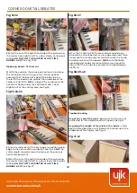
4)

 Plunge the cutter down through the comb slot to set 

the cutter depth to the marked pencil line, see fig 27. 

Attach the magnetic extraction at the right hand end 

of the support bar, see fig 28 or on a larger width board 

attach the right hand side stop to the right hand end of 

the jig to support the magnetic extraction. Alternatively 

the router’s in built extraction nozzle can be used, see fig 

29-30.

Continues over...

Summary of Contents for ujk 106843

Page 1: ...BOX FINGER JOINTS GROOVE HOUSING JOINTS THROUGH DOVETAILS SLIDING DOVETAILS HALF BLIND DOVETAILS CORNER DOVETAIL REBATES Code 106843 AT 22 03 2021 Universal Dovetail Jig F I N D O U T M O R E ...

Page 2: ... Clamps A 106843 1 Magnetic Extraction B 2 Comb Bar Support Arm C 1 Router Extraction Support Bar D 1 Comb Half Blind Sliding Template B E 1 Comb Through Dovetail Box Template A F 1 1 4 Shank 13 55mm Diameter Dovetail Cutter G 1 4 Shank 10 39mm Diameter Twin Flute Straight Pin Cutter G 1 4 Shank 12 5mm Diameter Twin Flute Straight Box Joint Cutter G 1 Magnetic Set Gauge H 6 Countersink Hex Screws ...

Page 3: ...nob WARNING KEEP TOOLS AND EQUIPMENT OUT OF REACH OF YOUNG CHILDREN KEEP WORK AREA AS UNCLUTTERED AS IS PRACTICAL UNDER NO CIRCUMSTANCES SHOULD CHILDREN BE ALLOWED IN WORK AREAS Make Sure you have read and fully understood the General instructions and safety precautions that is explained in your Router s owners manual Check the router cutter bit you are about to fit is the correct tool for the job...

Page 4: ...BLY SETUP 4 Assembly 7 8 9 6 4 2 3 1 D B K C I 5 Comb Template Lower the comb template down line up the counter sink holes with the holes in the comb bar support arms C Secure in place using four countersink Hex screws I ...

Page 5: ... the width of the timber increases in 1 2 measurement i e 5 5 1 2 6 6 1 2 etc as this will give a series of fully formed dovetails without part formed pins or sockets at the ends It is a good idea to identify the drawer pieces see fig B so that they are positioned correctly in the jig Fig B Router Cutter Fig C Fig D A selection of different makes of router guide bush adaptors 1 4 Shank 10 39mm Str...

Page 6: ...board use the cutter set line mark on the right of the comb a sharp pencil to mark a line at the top of the board see fig 04 3 Load in vertically the first board on the left of the jig pushing up to the underside of the comb centralising to the fingers see fig 05 Slide the side stop towards the right to make contact with the side of the material see fig 06 lock in place 4 Slide the horizontal boar...

Page 7: ...e lines to help find the fingers see fig 16 DO NOT LIFT THE ROUTER WHILST IT IS RUNNING 7 Remove both boards try for fit If the joint is too tight won t fit together with a light tap then raise the cutter very slightly approx 0 5mm and recut new boards see fig 17 Trouble shooting Joint too tight raise the cutter very slightly approx 0 5mm and recut new boards see fig 17 Joint too loose lower the c...

Page 8: ...of the jig see fig 01 move both side stops to a central position lock in place see fig 02 2 Mark a square line across the board where the centre of the groove slot will be load in clamp the board horizontally under the comb up against the left hand side stop see fig 03 04 05 3 Ensure that the comb is sat flat level on top of the board see fig 06 Use the wider part of the set gauge to ensure that t...

Page 9: ...ig 11 or on a larger width board attach the right hand side stop to the right hand end of the jig to support the work see fig 12 13 14 6 Start the cut at the right hand side of the jig moving the router from right to left see fig 15 16 in a slow steady continuous motion DO NOT LIFT THE ROUTER AT ANY TIME DURING A CUT NB if working in very hard wood a half depth cut may be required Trouble shooting...

Page 10: ...g 04 3 Ensure that the comb is sat flat level on top of the board see fig 05 Use the wider part of the set gauge to ensure that the marked square line is central to the dovetail comb slot see fig 06 Use the comb adjuster knobs to align adjust see fig 07 08 4 The cutter depth is optional will always be the same for both the dovetail slot the opposing tenon For the best aesthetic strength results se...

Page 11: ...al thickness position the router at the left side of the comb cutting from left to right in a slow continuous motion DO NOT LIFT THE ROUTER AT ANY TIME DURING A CUT see fig 22 23 With the board the same end up flip the board cut the other side see fig 24 25 26 Position the magnetic extraction to the left or you may prefer to use the router s extraction for best extraction results on this cut see f...

Page 12: ...see fig 02 Fig 06 07 Fig 09 Fig 08 Fig 03 04 05 Fig 01 02 2 Move the magnetic extraction then use the hex key provided to move the side stop to the left see fig 03 04 05 Load in vertically the first board on the left of the jig pushing up to the underside of the comb centralising to the fingers see fig 06 07 3 Ensure that the material markers on the comb are centralised to the top of the board loo...

Page 13: ...are at the front of the jig pins see fig 15 16 17 18 Load in vertically the pin board against the left hand side stop up against the underside of the comb see fig 19 20 Undo the comb lock knobs use the comb adjuster knob to align the finger line to the edge of the board see fig 21 22 2 Use the opposing board to mark a cutter depth set line on the material see fig 23 then plunge the straight cutter...

Page 14: ...g the adjuster knobs clockwise see fig 29 Try half a turn to start with Recut taking a very light skim try for fit again repeat if still too tight see fig 30 Trouble shooting Joint too tight move comb backwards recut Joint too loose move fingers forward recut new board Gaps at one end of the joint timber not square comb not sat flat on timber see fig 31 Excessive break out at the back of the cut a...

Page 15: ...provided to move the side stop to the left Load in vertically the first board on the left of the jig pushing up to the underside of the comb centralised to the fingers see fig 03 04 05 06 3 Undo the comb lock knobs use the comb adjuster knobs to ensure that the two finger lines on the comb are centralized to the top of the board look equal along the length see fig 07 08 09 4 Slide the side stop to...

Page 16: ...t fingers fully up through the comb centralise using the smaller part of the set gauge H provided and lock in place see fig 16 17 18 19 20 8 Slide side stop to the left to make contact with the board lock in place Remove the set up board replace with the board to be cut sliding it in against the side stop up against the underside of the fingers see fig 21 22 9 As before use the opposing board to m...

Page 17: ...ckness 12mm Max timber thickness 25mm Parts needed Template B sliding half blind 13 55mm Dovetail cutter 19mm or 15 9mm Guide bush For good corner edge alignment using 12mm 15mm thick boards both parts of this joint can be cut at the same time single pass It is recommended that other board thicknesses are cut in 2 passes 1 Attach comb B with the long groove slot at the front of the jig see fig 01 ...

Page 18: ...g 08 Use the comb adjuster knobs to align adjust see fig 08 4 Plunge the cutter down through the comb slot so that the tip of the cutter just meets the marked line see fig 09 Attach the magnetic extraction at the right hand end of the support bar see fig 10 5 Start the cut at the right hand side of the jig moving the router from right to left in a slow steady continuous motion see fig 11 DO NOT LI...

Page 19: ...e set gauge to position board edge to the centre of the comb slot see fig 25 26 Fig 19 20 Side Stop Side Stop 2 Mark a line thickness of the board see fig 23 load in the horizontal board Support board gainst the left hand side stop ensuring that the comb is sat flat on the board a support board with equal thickness to the cut board may be required to support the comb when using narrow boards see f...

Page 20: ... of the fingers see fig 41 Gap along the length of the joint on the inside cutter depth altered between cuts board not pushed up to the underside of the fingers see fig 42 Fig 31 32 Axminster Tool Centre Ltd Axminster Devon EX13 5PH axminstertools com ujk 2 Use the wider part of the set gauge to position board edge to the centre of the comb slot see fig 36 NB The cutter depth should remain the sam...

Reviews: