


18
: P
at
hfi
nd
er
PC C
lie
nt •
96
© 2017 Telos Alliance - Rev 1.2
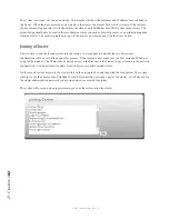
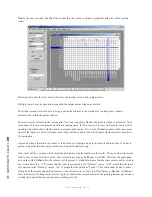
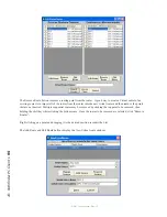
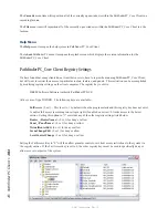
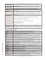
The View Virtual Routes window is where the specifics for a given virtual route may be edited and defined. Each
Virtual point is made up of any number of actual points from other routers. These points are listed in the list at the
top of the screen
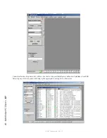
A given route point may only have a single route point making it a direct map to a point on another router. But it
also may have several router points tied to this single virtual point. This allows a single virtual point to include
audio, video, machine control, and GPIO points for a given device. The Remove Route button removes the selected
real route point from the virtual route point list. The Router Name and Router Point drop down lists provide access
to all of the actual routers and their points. Simply select the router and the route point which is to correspond to
this Virtual point and then click either Add Source/Destination or Change Source/Destination to either add a new
point or edit the currently selected point.
The Patch Name is the name of the Virtual Point in the Virtual Router, and the description field allows a description
to be created for the virtual route point. Clicking “Done” submits the Changes to the configuration.
The purpose of a Virtual Router is to provide an ordered subset of a real router where each point on the virtual router
corresponds to an actual point on a real router. Some more explanation may be needed to understand why some
points in the Virtual Router might have multiple corresponding points though. Here is an example.
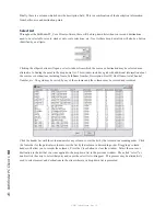
Radio station WXYZ is using Pathfinder Core PRO, and has already allowed discovery and therefore has both an
audio and a GPIO router. One of their automation systems has both a primary and a backup system - each with a
Livewire driver. While interfacing with a satellite link, the system needs to be able to react to and trigger GPIO
changes from a node on the network as well as audio. It does this by routing the node’s closures to the automation
system’s Axia driver which the automation system is monitoring. And when the automation trips closures on its
local drivers, those need to appear as GPOs on the remote node. Additionally, audio needs to be routed to and from
the automation system. When the station needs to switch from the primary automation system to the backup system,
all of these signals must travel together.
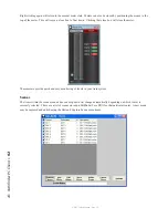
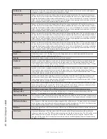
In order to accomplish this, a Virtual Router may be created. Create a new point in the Destination field (the device
input side) by clicking on the Add Route button under the Destinations list. Assign it a patch name of “Automation
System A”. Next, select the Audio router from the router name drop down combo. Select the correct audio point for
the first automation system’s input from the router Point drop down combo. Click Add Destination. Next, Select
the GPIO Router from the router name drop down combo. Select the correct GPIO input point for the Automation
system from the router point list that is now displaying the list of routes for the GPIO router since that is what is
selected above. Click Add Destination. Finally, click the “Done” button to add the point into the configuration.
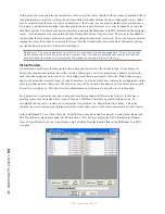
Repeat the same procedure under the Sources List (Device outputs) and make a point for the audio source - for the
sake of this example, we will use a satellite audio signal applied to a node. Also add the GPIO point as described
above. You could also create an output point for the automation system and an input point for the satellite, so
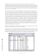
that routing could take place in both directions. Repeat this procedure for the second automation system. Finally,
once all desired points are created, click the Create/Close button to submit the new router design to the server or
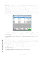
Pathfinder Core PRO. At this point, the Virtual router will then appear in the list of Routers in the Routers Menu.
Open the new virtual router.
Now if the engineers route Satellite Out to Automation System 1 In, the Audio and GPIO are routed simultaneously.


