


5 Trouble shooting
5.1 Preliminary checks
Before operating the positioner check the following:
1) Voltage
The positioner requires a 24 V DC (nominal), 4-20 mA current loop.
Current range: 3.2 mA to 22 mA, accordingly to the following table (Namur NE43):
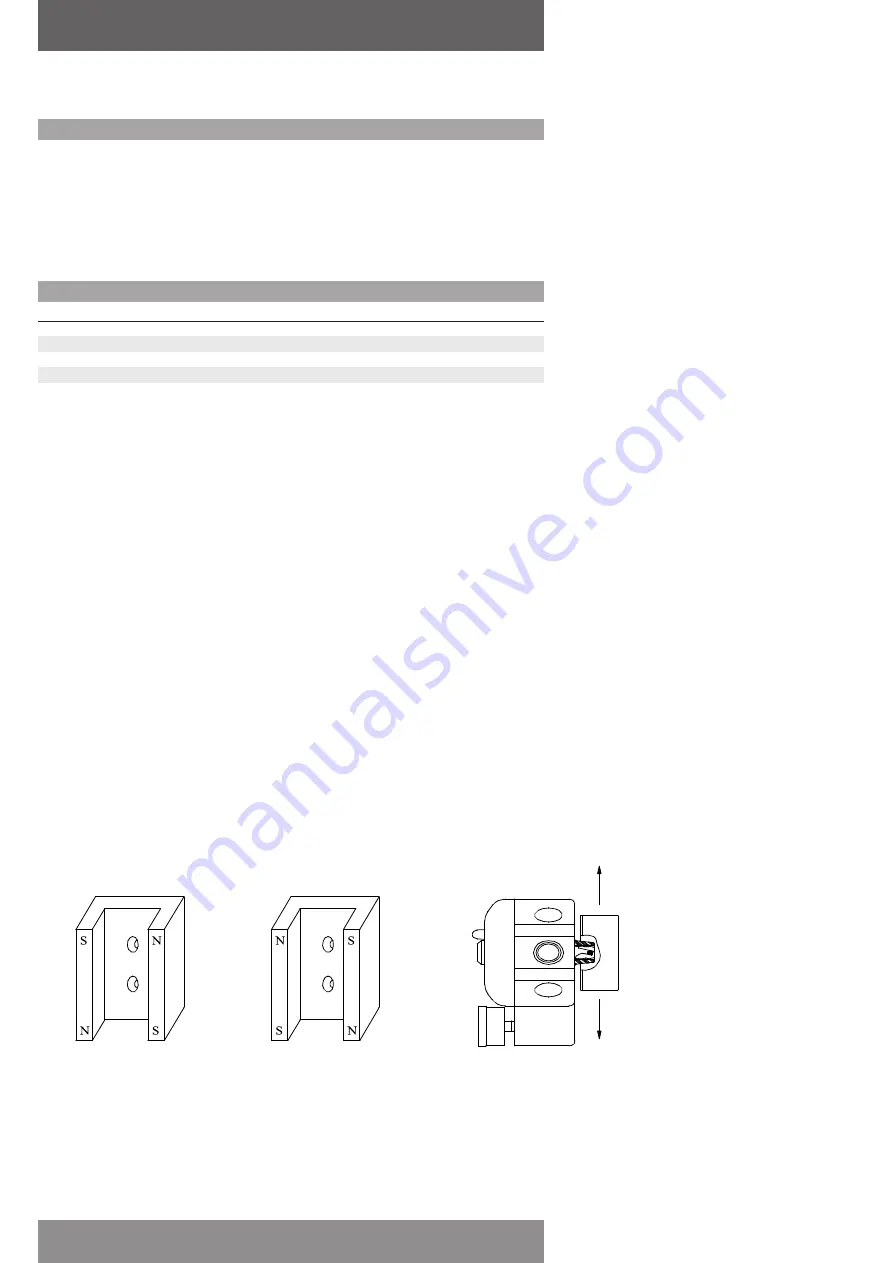
Polarities of magnetic feedback assemblies
(for linear smartcal positioners)
FAIL-DOWN
(Actuator fails in direction A)
FAIL-UP
(Actuator fails in direction B)
Direction B
Direction A
Figure 5-1
page 24
AVID SmartCal valve positioner
Installation & operating instructions
Input current (mA)
Electronics
Spool valve
HART® Comm
0.0 ≤ I < 3.2
OFF
OFF
OFF
3.2 ≤ I < 3.5
ON
OFF
OFF
3.5 ≤ I < 3.8
ON
OFF
ON
3.8 ≤ I ≤ 20.5
ON
ON
ON
I > 20.5
ON
ON
ON
2) Electrical connection
Check the polarity of the 4-20 mA current loop. The SmartCal terminal strip visually designates the
positive and negative terminal points for connection with a ‘+’ and ‘-’, respectively.
3) Pneumatic connection
Single acting:
Output port 1 should be piped to drive the actuator away from the valves fail position. Output port
2 should be plugged. (See Section 2.6)
Double acting:
Output port 1 should be piped to drive the actuator away from the valves fail position. Output port
2 should be piped to drive the actuator towards the valves fail position. (See Section 2.6)
4) Magnetic feedback to the positioner
Rotary positioner:
The magnetic beacon should be set in the proper orientation, based on the direction of failure.
(See Section 2.1 or 2.2)
Linear positioner:
The magnetic assembly supplied with the positioner should correspond to the stroke length and
failure direction of the actuator. To make sure you have the appropriate magnet assembly, check
the part. The stroke length and failure direction should be printed on the part. On older SmartCal’s
the magnet assembly is not printed with this information, although there should be a serial
number. Contact the factory with the serial number to verify that it is correctly matched to the
actuator. (See Figure 5-1 & Figure 5-2).


