background image

FINE TUNE

Up arrow

(exit calibration)

Set 12 mA

Press CAL Key

Down arrow

(from previous menu)

Down arrow

(to next menu)

Down 

arrow

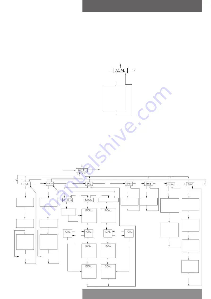
3.3 Automatic calibration

The automatic calibration (ACAL) performs several self-adjustments, as well as a zero calibration, 
a span calibration, and tunes the positioners PID gain settings. Enter and start the automatic 
calibration from the menu level. From the menu level press the down arrow button until ACAL is 
shown on the display (ACAL routine shown below).

Note:

 Automatic calibration requires an input current of 12 mA.

Auto calibrate*

* 1.  Sensor calibration

2. Low span calibration

3. High span calibration

4. Transducer calibration

5. Auto PID calibration

3.4 Proceed to exiting calibration or perform advanced calibration

At this point the calibration of the positioner is complete. The automatic calibration that was 
performed in Section 3.3 is adequate for most applications. If no advanced calibration is required 
proceed to Section 3.5 to exit calibration. If the user requires to use the advanced settings to fine 
tune the positioner he may proceed with the remainder of this step and perform adjustments and 
calibrations in the Manual Calibration Menu (MCAL). From the menu level press the down arrow 
button until MCAL is shown on the display (MCAL routine shown below).

Up arrow

(exit calibration)

Down arrow

(from previous menu)

Down arrow

(to next menu)

Up arrow

Down 

arrow

Up arrow

Up arrow

Up arrow

Up arrow

Up arrow

Press CAL key

Press CAL key

Press CAL key

Press CAL key

Press CAL key

Press CAL key

Press CAL key

Press CAL key

Press CAL key

Press CAL key

Press CAL key

Press CAL key

Press CAL key 

when complete

Press CAL key

Press CAL 

key

Set 12 mA

Press CAL key

Set 12 mA

Press CAL key

Press CAL key

Press CAL key

Press CAL key

Press CAL key

Press CAL key

Press CAL key

Press CAL key

when complete

Press CAL key 

when complete

Press CAL key 

when complete

Press CAL key 

when complete

Press CAL key

Down 

arrow

Down 

arrow

Down 

arrow

Down 

arrow

Press CAL key

Down 

arrow
Down 

arrow

Down 

arrow
Down 

arrow

Down 

arrow

Down 

arrow

Down 

arrow

Down 

arrow

Down 

arrow

Set mA for 

zero position

Set mA for 

span position

Sensor 

calibration

Transducer 

calibration

Set 4.0 mA

Use up & down arrow 

keys to set to zero 

input current

Set 20.0 mA

Use up & down arrow 

keys to set to span 

input current

Low/zero 

calibration

Span 

calibration

Automatic 

PID routine

Adjust using 

up & down 

arrow keys

(1-20)

Adjust using 

up & down 

arrow keys

(1-255)

Adjust using 

up & down 

arrow keys

(1-5)

Adjust using 

up & down 

arrow keys

(1-255)

Adjust using 

up & down 

arrow keys

(1-255)

Adjust using 

up & down 

arrow keys

(1-20)

Optional:

select arbitrary 

zero using up & 

down arrow keys

Optional:

select arbitrary 

span using up & 

down arrow keys

Read transmitter 

value & use up & 

down arrows to 

enter the present 

zero value

Use up & down 

arrows to enter the 

desired zero current, 

typically 4.0 mA

Read transmitter 

value & use up & 

down arrows to 

enter the present 

span value

Use up & down 

arrows to enter the 

desired span current, 

typically 20.0 mA

Special note flow capacity

SmartCal standard flow design is suitable 
for actuator swept volumes of a minimum 
40 inch

3

 (0.65 liters) to a maximum of 600 

inch

3

 (9.8 liters) for proper auto calibration 

functionality. It should also be noted that 
this is to be used as a general guideline only. 
The actuator/ valve package dynamics would 
dictate the success of the auto calibration 
routine and could be compromised by the 
following: instrument air supply volume 
capacity, actuator sizing, tubing size and 
actuator/valve health.
SmartCal optional high flow design is suitable 
for actuator swept volumes of a minimum 
200 inch

3

 (3.3 liters) to a maximum of 1000 

inch

3

 (16.4 liters) for proper auto calibration 

functionality. It should also be noted that 
this is to be used as a general guideline only. 
The actuator/ valve package dynamics would 
dictate the success of the auto calibration 
routine and could be compromised by the 
following: instrument air supply volume 
capacity, actuator sizing, tubing size and 
actuator/valve health.

OFF

Press CAL key

ON

ON

OFF

page 13

AVID SmartCal valve positioner

Installation & operating instructions

Summary of Contents for SmartCal Series

Page 1: ...ctions 22 4 5 Print 23 5 Trouble shooting 24 5 1 Preliminary checks 24 5 2 FAQ 25 6 Specifications 26 7 Error codes 26 8 Exploded parts list 27 Appendices A Procedure to adjust Err 3 setting 28 B Proc...

Page 2: ...ilure condition occurs an error message is displayed on the local liquid crystal display 1 2 Principle of operation Unlike conventional positioners the SmartCal positioner feeds back valve position wi...

Page 3: ...d sensors The SmartCal positioner has the capability to monitor its operation If an error or failure condition occurs it will be displayed on the local LCD through the HART interface and displayed on...

Page 4: ...of the positioner Actuator in fail position ModMount Supply Port 1 Port 2 TURNS COUNTER CLOCKWISE from fail position TURNS CLOCKWISE from fail position 2 1 Mounting positioner on a rotary actuator Co...

Page 5: ...oner sensor TURNS COUNTER CLOCKWISE From fail position TURNS CLOCKWISE From Fail Position 2 2 Mounting remote positioner on a rotary actuator Condition 1 Actuator fails in a clockwise direction Turns...

Page 6: ...y unscrewing 2 mounting screws Wire the positioner sensors back to the positioner using the cable provided see Figure 2 3 4 Conductor cable cut to required length and run through conduit M20x1 5 1 2 N...

Page 7: ...embly to the stem of the actuator A coupler block normally is needed to extend the magnet assembly outside the yoke area and into the sensing range of the magnetic pick up unit Step 2 Fasten the mount...

Page 8: ...n the actuator s yoke that lines up with the red arrow on the magnet assembly 3 Place a third mark on the yoke centered between the upper and lower limit marks 4 Lastly mount the positioner to the bra...

Page 9: ...ribed in Section 3 3 Step 1 Step 2 Mount the position sensor housing so that the conduit entry faces away from the diaphragm or cylinder See Figure 2 5 A Step 3 Mount positioner at a remote location N...

Page 10: ...to decrease in outlet port 2 of the positioner Note Air supply to the positioner must be clean dry oil free instrument air 5 microns per ISA S7 3 and ISO 8573 1 Maximum supply pressure is 8 3 bar All...

Page 11: ...ally connected suitable to the rated data via a certified isolating interface zener barrier placed outside the hazardous areas 4 For ambient temperatures below 10 C and above 60 C use field wiring sui...

Page 12: ...menu Down arrow to next menu Up arrow Up arrow Down Down Down Down Down Down Down Down Down Quick opening flow Equal percentage flow Rotary valve Fail open Use up down arrows to select open speed 01...

Page 13: ...row Down arrow Press CAL key Down arrow Down arrow Down arrow Down arrow Down arrow Down arrow Down arrow Down arrow Down arrow Set mA for zero position Set mA for span position Sensor calibration Tra...

Page 14: ...s complete before being able to exit calibration The up arrow key can be used as described above to move to the Menu level and then to exit CAL mode 3 6 Manual override of input signal via on board ke...

Page 15: ...Sensor calibration 5 Trnd Transducer calibration 6 mA Milliampere calibration 7 Xmr Transmitter calibration Menu 3 Cofg configuration Entering this menu allows you access to the following five configu...

Page 16: ...libration is a self adjustment that sets the positioners Hall effect circuitry This is automatically done during the ACAL automatic calibration routine The sensor calibration also shows up under the M...

Page 17: ...1 which is equivalent to a deadband of 0 5 The value 20 highest deadband value has a range of 20 which is equivalent to a deadband of 10 LCD This feature configures LCD timeout The range is 1 to 60 m...

Page 18: ...or the connection to the 4 20 mA controls see the schematic in appendix D The SmartCal DTM can be used with several FDT frame applications If you don t have any you can use the PACTware configuration...

Page 19: ...D values or tune them after auto calibration The positioner is configured for 0 100 control By changing the parameters in the Travel Limit Setting menu you can alter the lower and upper limits Only a...

Page 20: ...alve movements The end result is the number of full open close cycles The value Accum DB is the minimum stroke that can be counted If the counted value exceeds this limit the alarm will be activated T...

Page 21: ...ware optional This facilitates the comparison of curves and the preparation of reports 4 3 Diagnosis Selection of Diagnosis produces an overview of all SmartCal alarms and statuses It shows proper ope...

Page 22: ...on Capture Analog Digital and Digital tuning Each selection has its own menu Please follow these instructions in order to carry out the appropriate calibration The Analog selection uses the mA signal...

Page 23: ...e test procedure will be cancelled and a full auto or manual calibration has to be carried out Note while executing certain functions e g calibration communication between pc and SmartCal may stop and...

Page 24: ...ic connection Single acting Output port 1 should be piped to drive the actuator away from the valves fail position Output port 2 should be plugged See Section 2 6 Double acting Output port 1 should be...

Page 25: ...linear is desired enter calibration and make this change See Calibration instructions Section 3 5 After removing power to the positioner there is full pressure to output port 1 and zero pressure to o...

Page 26: ...gnostics HART protocol software utilizing HART protocol AMS or FDT DTM Enclosure Material Engineered resin Class of equipment NEMA type 4 4x or IP66 Weight 3 3 Kg Air connections 1 4 NPT or BSP Std fl...

Page 27: ...assembly 3 1 Electronics module assembly 4 1 Transducer assembly 5 1 Housing assembly 6 1 Manifold assembly 7 1 Direct mount assembly 8 Exploded parts list Dimensions mm Front view ModMount Namur pat...

Page 28: ...e Error 3 for an explicit pressure value loosen the lock nut on the adjustment screw and gently turn the screw clockwise as far as it will go Do not force the screw past its limit or the Error 3 diaph...

Page 29: ...ing and ground cable Remove the screw that secures ground cable See Figures below 3 Remove the canister with electronics from SmartCal enclosure Canister cover Indicated screw secures cover and housin...

Page 30: ...LCD will display a failure message and the transmitter output if so equipped will go to pre determined current to indicate the failed state The transmitter output can be configured to go to 3 4 mA or...

Page 31: ...he 4 20 mA signal generator Note The transducer operates between 0 and 3 3 mA Therefore make sure when turning on the current supply s power the current is turned down within this range Applying a cur...

Page 32: ...ntain optimum positioner performance To clean the spool valve the spool piece needs to be removed see diagram below Prior to removing the spool make sure the positioner is out of service and all air p...

Page 33: ...d twisted pair Belden 8762 or equivalent Maximum distance from HART Multiplexer to positioner is 1800 m 6000 feet Shield shall be connected to ground at one point only in order to avoid ground loops a...

Page 34: ...ram Supply air Pilot air assembly Outlet port 2 Outlet port 1 20 micron air filter Air to actuator air out of transducer Air to transducer Pilot air transducer page 34 AVID SmartCal valve positioner I...

Page 35: ...ed apparatus used in an approved configuration such that A SmartCal Vmax Voc and Vt of associated apparatus B SmartCal Imax Isc and It of associated apparatus C Ci of SmartCal cable capacitance Ca of...

Page 36: ...riers may be used where both channels have been certified for use together with combined entity parameters The following conditions must be satisfied Voc or Vo Vmax or Ui Ca Ci C Cable Isc or Io Imax...

Page 37: ...sociated apparatus E In cases where the Rosemount 275 HART Communicator is connected between the associated apparatus and the SmartCal cable inductance should be determined in accordance with Rosemoun...

Page 38: ...intrinsically safe associated apparatus ground 4 Rosemount 275 HART Communicator is NOT FMRC approved for use in Class II and III Hazardous Locations 5 For Class II and III locations where rigid metal...

Page 39: ...pparatus ground 4 Rosemount 275 HART Communicator is NOT FMRC approved for use in Class II and III Hazardous Locations 5 For Class II and III locations where rigid metal conduit is not used seal Smart...

Page 40: ...r Vo Vmax or Ui Ca Ci C Cable Isc or Io Imax or Ii La Li L Cable 2 Associated apparatus manufacturer s installation drawing must be followed when installing this equipment 3 Control equipment connecte...

Page 41: ...Use the down arrow to change No to Yes To begin Factory reset procedure press the Cal button 4 When mA METER CALIBRATION appears release the Up arrow button 5 After releasing the Up arrow button you w...

Page 42: ...witch Alert 1 OpnLmtSw Alert 2 ClsLmtSw Alert Basic Config 1 Valve Type 2 Flow Type 3 Display Mode 4 Control Mode Cal Config 1 PID Parameters 2 Slew Speed 3 Setpoint Capture 4 Limit settings 5 Digital...

Reviews: