


The SmartCal has a number of alarms. Malfunctions can easily be detected on the display and it
is even possible to prevent downtime. The ‘cycle count’ function registers how often the SmartCal
changes direction. Every time the direction changes and a stroke is made that exceeds the defined
‘Cycle DB’ (DB is dead band), the number is increased by 1. As soon as the ‘Cycle Count’ exceeds
the ‘Cycle Limit’ and the ‘Cycle Alert’ is enabled, the alarm will be activated.
With the ‘Cycle Count’ you can detect any oscillations in the control loop. The cause could be
incorrect parameter values, but also valve wear. If the valve gets stuck, the torque required
increases. As soon as the valve begins to move, the torque will be too great and the valve travels
beyond the set position. As a result, the positioner will move the valve into the opposite direction.
In this way, the control loop becomes unstable (begins to oscillate), which leads to production
loss. With the ‘Cycle Alert’ alarm you will be notified in time.
To verify if the positioner operates in its control range, the functions ‘Travel High’ and ‘Travel Low’
have been included. If the position exceeds these limits by more than the ‘Travel DB’, the ‘Travel
Alert’ alarm will be activated.
In addition to the ‘Cycle Count’ alarm, the ‘Travel Accumulated Count’ is also a valve wear
indicator. The ‘Accum. Count’ counts the number of valve movements. The end result is the
number of full open/close cycles. The value ‘Accum. DB’ is the minimum stroke that can be
counted. If the counted value exceeds this limit, the alarm will be activated.
The ‘Deviation Setting’ generates an alarm if the difference between the PV (process value)
and the SP (setpoint) exceeds the selected value. The ‘Deviation’ alarm is activated only if the
‘Deviation Alert’ is enabled.
Although mentioned in the software, the ‘Limit Switch Settings’ are not used.
The ‘Device’ menu presents supplier and model information and also the hardware and software
revision. The ‘Description’ and ‘Date’ fields are available for information such as valve number and
calibration date. This information is saved in the SmartCal and is available for future reference.
The ‘HART®’ menu displays specific information of the HART® communication. The ‘Tag’ field can
be used for reference and the ‘Polling-Address’ can be changed if the SmartCal is connected in a
network.
4.2 Measurement data
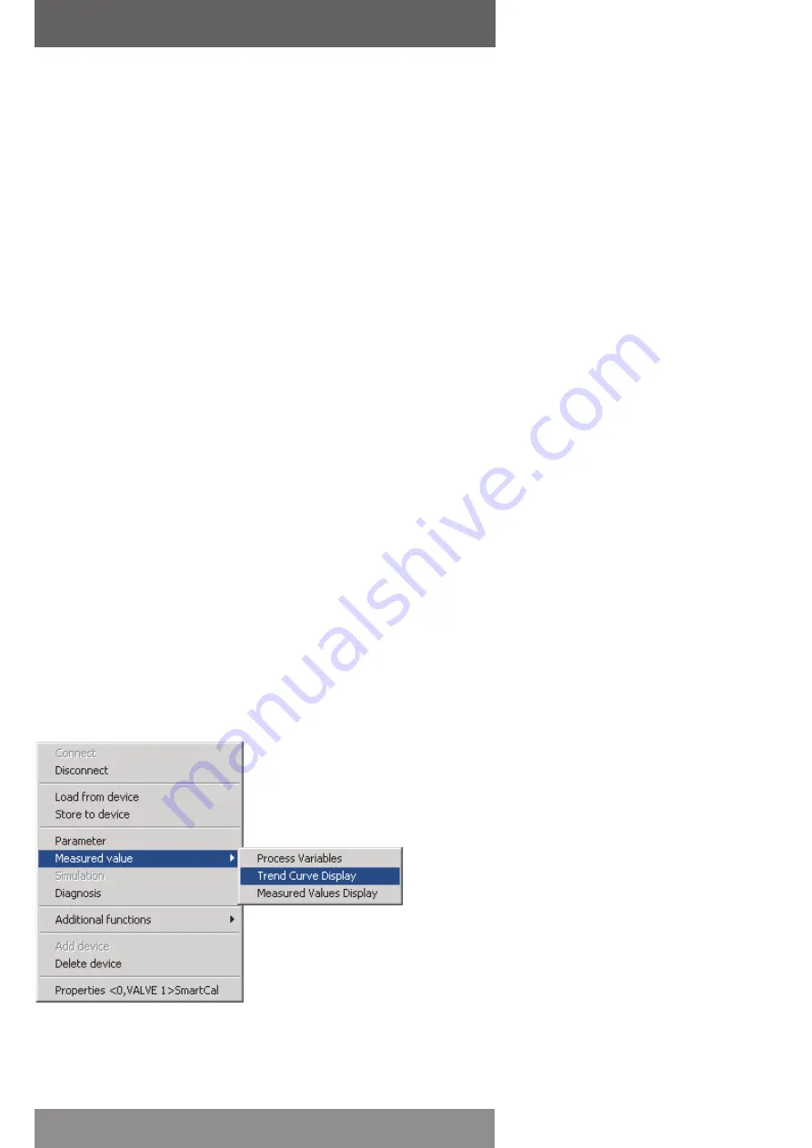
The HART® communication allows retrieving parameter values during operation. The ‘Measured
Value’ menu presents an overview of all parameters (‘Process Variable’) and a trend curve or bar
graph of the most important parameters.
The ‘Process Variables’ screen displays all variables as a dashboard. The variables are displayed,
but cannot be changed.
The trend curve and bar graph show the most important parameters, i.e. setpoint, valve position,
air pressure and 4-20 mA input/output signal of the SmartCal.
page 20
AVID SmartCal valve positioner
Installation & operating instructions


