


S4 Installation Guide
16
Positioning Cables
Before installing modules, make sure all power and Ethernet cables are positioned as needed in each chassis.
Frames include cables pre-positioned for standard configurations, with multiple pairs of power and Ethernet cables already fed into
each chassis from the built-in PDB (Power Distribution Board) and Ethernet switch. These pairs are ready for connection to Chan-
nel Strip, Display, and master modules.
Display Modules and certain Option module configurations require pre-positioning cables as described below.
If your system includes Display Modules, do the following to remove port covers and position cables:
1
Remove the black plastic coverings from the small openings on the back of each chassis where you will install Display Modules.
2
Feed one pair of Ethernet and power cables through the hole in the back of each chassis where you will be installing Display
Modules. If necessary, feed cables from a neighboring chassis through holes in the chassis wall(s).
Be sure to position enough cables for all Option modules, if any, in their chassis. If you are only installing a single Option Module
into a chassis you should not need to position any additional cables. However, if you will be filling a chassis with three Option mod-
ules
and
a Display Module make sure there are four pairs, total, of power and Ethernet cables in that chassis.
If your system includes any Option modules, do the following before proceeding:
1
Identify the chassis into which the Option modules will be installed.
2
Make sure there is an available pair of Ethernet and power cables for each module that will be installed in that chassis.
3
If necessary, feed available built-in cables from a neighboring chassis through the holes in the chassis wall(s) to the Option mod-
ules chassis.
• Cable ties secure cables to the bottom of the chassis. If necessary, cut one or more cable ties that are closest to the ends of ca-
bles, then route the cables between chassis as needed.
• A bag of new cable ties is also included with the frame. Use these to re-secure cables in their new chassis location(s).
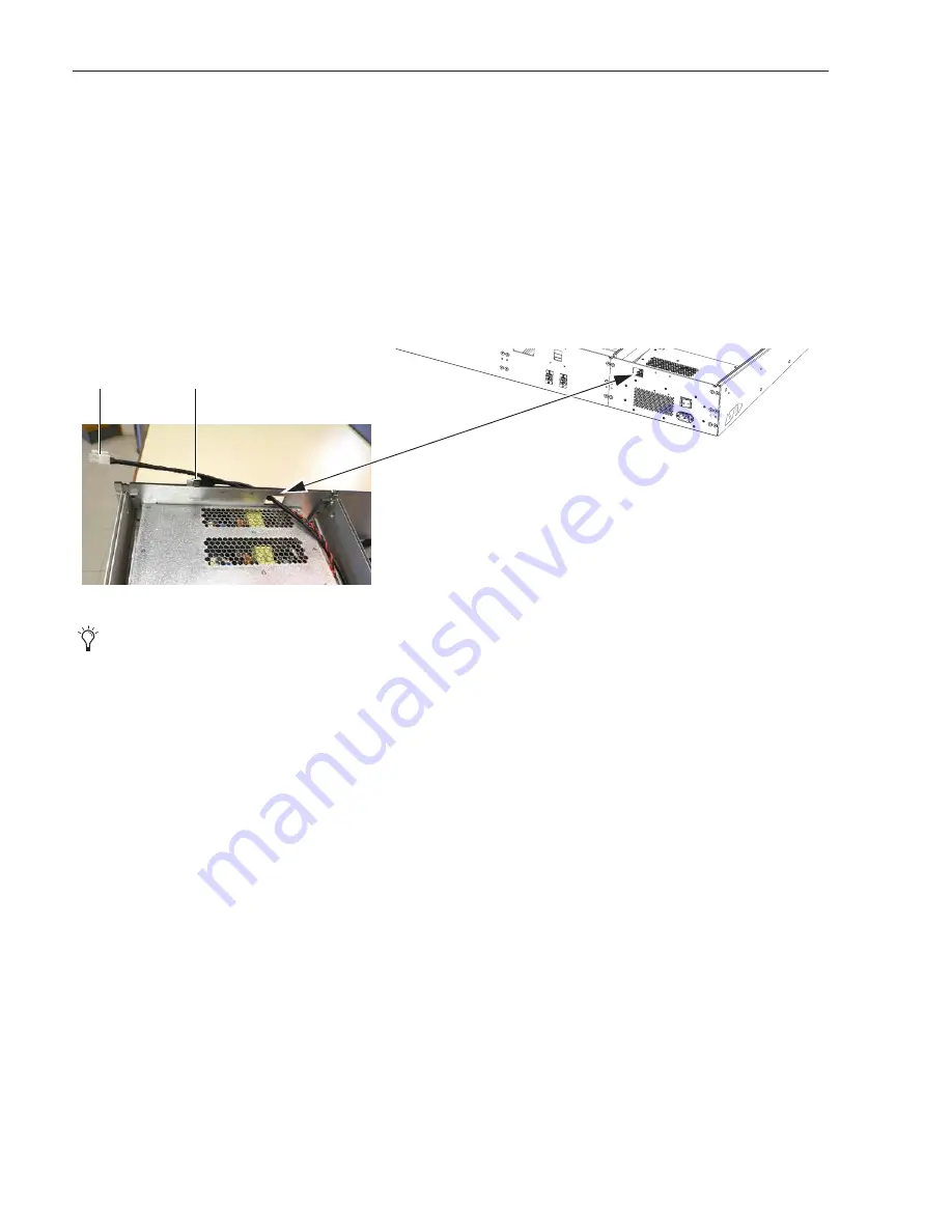
Figure 4. Routing Ethernet and power cables for a CDM
You can also remove the large black plastic covering from the opening in the back of the chassis where you plan to install the Mas-
ter Module, or wait until you are installing the Master Module as instructed later in this guide.
Ethernet
Power
Summary of Contents for S4
Page 1: ...Avid S4 Installation Guide ...
Page 4: ......
Page 7: ...Part I Introduction ...
Page 8: ......
Page 17: ...Part II Hardware Assembly ...
Page 18: ......
Page 35: ...Part III Software Installation ...
Page 36: ......
Page 42: ...S4 Installation Guide 36 ...
Page 43: ...Part IV Reference ...
Page 44: ......
Page 59: ......