background image

Appendix B: Compliance

81

Safety Compliance

This equipment has been tested to comply with safety certifications in accordance with: UL 60065: 2015, 8th Ed., CAN/CSA C22.2 No. 60065:16, 
EN 60065:2015-A1/A11:2017, IEC 60065:2014.

Avid Technology Inc., has been authorized to apply the appropriate NRTL mark on its compliant equipment.

Power Safety Input Rating

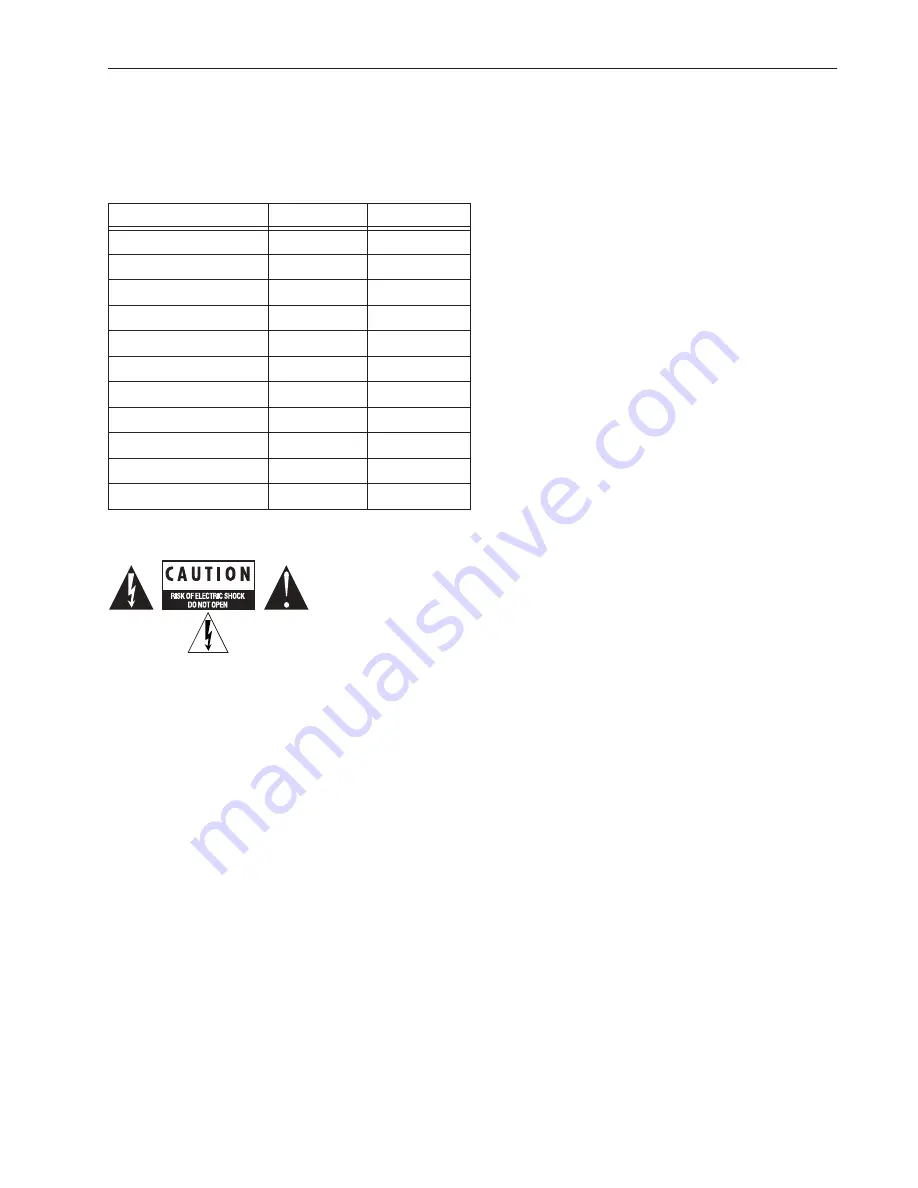
Warning

Important Safety Instructions

1) Read these instructions.

2) Keep these instructions.

3) Heed all warnings.

4) Follow all instructions.

5) Do not use this equipment near water.

6) Clean only with dry cloth.

7) Do not block any ventilation openings. Install in accordance with the manufacturer’s instructions.

8) Do not install near any heat sources such as radiators, heat registers, stoves, or other equipment (including amplifiers) that produce heat.

10) Protect power cords from being walked on or pinched particularly at plugs, convenience receptacles, and the point where they exit from the equipment.

11) Only use attachments/accessories specified by the manufacturer.

12) For products that are not rack-mountable: Use only with a cart, stand, tripod, bracket, or table specified by the manufacturer, or sold with the equipment. When 
a cart is used, use caution when moving the cart/equipment combination to avoid injury from tip-over.

13) Unplug this equipment during lightning storms or when unused for long periods of time. 

14) Refer all servicing to qualified service personnel. Servicing is required when the equipment has been damaged in any way, such as power-supply cord or plug 
is damaged, liquid has been spilled or objects have fallen into the equipment, the equipment has been exposed to rain or moisture, does not operate normally, or 
has been dropped.

15) For products that are a Mains powered device: 

The equipment shall not be exposed to dripping or splashing and no objects filled with liquids (such as vases) shall be placed on the equipment. 

Warning! To reduce the risk of fire or electric shock, do not expose this equipment to rain or moisture. 

Do not defeat the safety purpose of the polarized or grounding-type plug. A polarized plug has two blades with one wider than the other. A grounding type plug has 
two blades and a third grounding prong. The wide blade or the third prong are provided for your safety. If the provided plug does not fit into your outlet, consult an 
electrician for replacement of the obsolete outlet.

Avid S4/S6 Power Ratings per Module

Name

Model Number

Power Rating

Automation Module

9100-65496

12Vdc, 1.5A

Channel Strip Module

9100-74073

12Vdc, 6.9A

Display Module

9100-65500

12Vdc, 1.8A

Fader Module

9100-65444

12Vdc, 5.0A

Knob Module

9100-65443

12Vdc, 1.8A

Master Joystick Module

9100-65757

12Vdc, 0.7A

Master Module M10

9100-65497

12Vdc, 6.7A

Master Module M40

9100-65508

12Vdc, 6.7A

Master Module Universal

9100-74069

12Vdc, 6.7A

Master Post Module

9100-65765

12Vdc, 0.8A

Process Module

9100-65445

12Vdc, 1.3A

Summary of Contents for Pro Tools S6 Master Post Module

Page 1: ...Avid S6 Installation Guide ...

Page 2: ...ces Bonjour the Bonjour logo and the Bonjour symbol are trademarks of Apple Computer Inc Thunderbolt and the Thunderbolt logo are trademarks of Intel Corporation in the U S and or other countries This product may be protected by one or more U S and non U S patents Details are available at www avid com patents Product features specifications system requirements and availability are subject to chang...

Page 3: ...safety purpose of the polarized or grounding type plug A polar ized plug has two blades with one wider than the other A grounding type plug has two blades and a third grounding prong The wide blade or the third prong are pro vided for your safety If the provided plug does not fit into your outlet consult an electrician for replacement of the obsolete outlet 16 For products containing a lithium bat...

Page 4: ......

Page 5: ...Part II Frames Chapter 3 Assembling Legs 13 Unpack the Leg Frames 13 Attaching the Back Beam 14 Attaching the Front Beam 15 Attaching the Back Corner Brackets 16 Attaching the End Brackets 17 Leveling the Leg Frame 17 Tighten All Fasteners 18 How to Proceed 18 Chapter 4 Assembling Frame Chassis 19 Before You Begin 19 Assembling the Chassis 21 Attaching the Back Feet 25 Attaching the Bolster 28 Ins...

Page 6: ... 59 How to Proceed 60 Chapter 7 Confirming Installation and Updating Software 61 Starting Up and Shutting Down 61 S6 Software Activation 62 Logging in as Administrator and Updating Master Module Software 62 Activating Your Software License 63 Installing S6 Supporting Software 64 How to Proceed 65 Chapter 8 Completing the Hardware Assembly 67 Installing Fill Panels 67 Installing Compression Panels ...

Page 7: ...Part I Introduction ...

Page 8: ......

Page 9: ...fter assembly Identify and organize the packages that make up your purchased system see Figure 1 to simplify the assembly process All re quired tools are in the Side Covers package see What s Included on page 2 1 Master Module Includes this guide and your Master Module 2 Frame Components Chassis kits Side Covers Bolster and Rear Covers number and type vary depending on configuration Leg Frames Pro...

Page 10: ...sembly What s Included The Master Module package contains the following items Tools The following tools are required for assembly of the S6 frame and are included in the Side Covers package Hex M2 5 Hex M3 Hex M4 Hex M5 Hex M6 Phillips screwdriver 1 long Phillip screw driver 2 Small flat screw driver Legs The following tools are included with the Leg Set package not all systems include Legs One op...

Page 11: ...e Activation Card and follow the instructions to Activate required and Register optional but highly recommended included in the pouch in the same binder as this guide As soon as you have assembled your S6 system and confirmed a successful hardware installation activate your S6 system software on line As instructed later in this guide you must use the System ID on the included S6 System Software Ac...

Page 12: ...d the latest online manuals browse the Compati bility documents for system requirements search the online Knowledge Base or join the worldwide Avid user community on the User Conference https www avid com learn and support For S6 support trouble shooting and downloads visit http avid force com pkb articles faq Avid S6 Support Training and Education Study on your own using courses available online ...

Page 13: ...e connected S6 M10 Systems Include an M10 Master Module that supports up to 13 other S6 modules and up to two attached workstations S6 M10 systems accommodate 8 to 24 faders per frame and 1 Expand Zone Attention Track Knob Module and are suitable for smaller configurations Display Modules are not supported on S6 M10 systems S6 M10 Plus Systems Include an M10 Master Module with M10 Plus license tha...

Page 14: ...le The Master Joystick Module MJM provides two touch sensitive joysticks a central pan display dedicated panning mode switches and other displays and controls Master Post Module The Master Post Module is a traditional film monitoring panel that lets you switch track monitoring between input sources and punch tracks into and out of record A comprehensive Speaker Monitor Control section is provided ...

Page 15: ...n be installed in each chassis in the larger M40 systems only M10 M10 Plus systems support one additional Knob Module for Ex pand Zones Attention Track Knob Module while M40 and Master Mod ule Universal based systems support two Attention Track Knob Modules Display Module M40 and M10 Plus Systems Only Display Modules are installed above channel modules Each Display Module provides a large display ...

Page 16: ...es can also be placed below a Process Module Frame Chassis Small support one Knob Module per chassis Frame Chassis Large support up to two Knob Modules per chassis M40 or M10 Plus based systems also support Display Modules Not all slots need to contain modules Fill panels are available to cover un used slots and to allow smaller modules to be placed in slot 1 The first two sections show standard a...

Page 17: ...nged in any order left to right For example in an S6 M10 16 5 system 16 faders with five knobs per strip the master section modules can be located in three possible locations as shown below Example 1 S6 M10 16 5 with master section at far right Example 2 S6 M10 16 5 with master section in the center Example 3 S6 M10 16 5 with master section at far left ...

Page 18: ...ystem includes one then proceed to Part II Frames Figure 2 Supported arrangements of modules per chassis Display Modules not shown Supported Module Configurations Legend Module Arrangement per Chassis 1 None empty chassis for Master Meter Modules Fill Panels and or the Producers Desk option 2 Master Module in slots 1 and 2 3 Automation Module in slot 1 and Master Module in slots 2 and 3 standard m...

Page 19: ...Part II Frames ...

Page 20: ......

Page 21: ... secure it with fasteners do not fully tighten the fasteners Then attach the Back Corner Brackets and End Brackets Leg Frame Join Module and Leg Frame Extension The Leg Frame Join option lets you join two or more S6 Leg Frames together to form a larger system The Leg Frame Extension lets you add one chassis to each end of a Leg Frame If your system includes either of these options refer to the doc...

Page 22: ...asteners and washers included per mount secure the Beam at each end Do not tighten down fasteners all the way until both beams and both Back Corner Brackets are in place 3 Make sure the Beam sits flat on the top of the legs as shown in Figure 3 If necessary move the legs in or out Have someone help hold the components while you position the Beams on the Legs and attach the fasteners Figure 2 Attac...

Page 23: ...eam so that the pins on the top are closer to the center of the frame 2 Using four fasteners and washers included per mount attach the Beam across the front of the Legs as shown in Figure 4 Do not tighten the fasteners fully Figure 4 Attaching the front Beam to the Legs orientation of pins shown at upper left Not to scale M8x30 7760 30606 00 Fastener M8 WSHR 7760 30609 00 Washer 6mm Hex Tool ...

Page 24: ...fully 2 Attach the Back Corner Brackets to the legs as shown in Figure 5 using four more fasteners and washers included per bracket Align the pins on the brackets with the holes in the top of the Legs Do not tighten the fasteners fully Figure 5 Attaching the Back Corner Brackets bracket to Beam shown at upper left bracket to leg shown at lower left Not to scale M5x15 7760 30604 00 Fastener M5 WSHR...

Page 25: ...ou add a chassis to the left and or right end of a Leg Frame If your system includes a Leg Frame Extension refer to its included documentation to install it Leveling the Leg Frame To level the Leg Frame 1 Start at the back of the frame either end and make sure the back beam sits flat on top of the Leg as shown in Figure 3 2 Starting at either end place a level not included on the top of the leg be...

Page 26: ... or right legs as necessary Repeat for the back beam Tighten All Fasteners To complete the Leg Frame assembly 1 At the back of the frame either end make sure the beam sits flat on the leg and tighten the 4 fasteners that secure the beam to the leg from underneath then tighten the 4 fasteners of the Back Corner Bracket Repeat for the other end of the back beam 2 At the front of the frame either end...

Page 27: ...ckage and remove the included Frame Toolkit labeled 7020 38627 00 2 Locate and unpack all Frame Chassis components and place them near the work area 3 Identify each component see Figure 11 then note whether your Frame Chassis are Large or Small Some steps in the assembly process vary depending on the depth Large or Small of your Frame Chassis as noted in these instructions Figure 10 Frame componen...

Page 28: ...y Chassis Small or Large The standard chassis kit is identical to the chassis shown in Figure 11 and Figure 12 The Inlay Chassis kit is nearly identical except for its special cutaway Side Wall and two piece T strip Other components of the Producers Desk include the Inlay Module panel Fill Panels Rear Covers and Compression Panels Cable Sets and fasteners Instructions for these components appear t...

Page 29: ...ttom Plate sits on top of the left edge of the Side Wall as shown in Figure 15 If your system includes a Producers Desk and you want to install it at the far right end of the frame attach the end Side Wall to the special Inlay Chassis as shown in Figure 16 For all other positions assembly is identical to standard chassis Just re member that the Inlay chassis cannot be the left most chassis it must...

Page 30: ...ake sure the pins on the top of the Beams align with and fit through the openings in the Chassis Bottom Plate Do not fully tighten the fasteners yet Figure 16 Attaching the end Side Wall to the Producers Desk Inlay Chassis for systems with a Producers Desk being installed at the far right end only Figure 17 Attaching the end Side Wall to the Back and Front Tie Plates Figure 18 Attaching the first ...

Page 31: ...is in place but do not tighten them fully 8 Attach the right edge of the second chassis Bottom Plate to the left edge of the Side Wall of the first chassis using three 1 Phillips screws as shown in Figure 20 Do not tighten the screws fully Figure 19 Attaching the first two chassis top view at left and front view at right Figure 20 Securing the Chassis Bottom Plate of the first chassis to the Side ...

Page 32: ...e to the next section Figure 22 shows an example illustration of four assembled chassis a 24 fader system Important Figure 21 Securing the Back and Front Tie Plates of the first chassis to the Side Wall of the second chassis cables not shown If your system includes a Producer s Desk option see the Producer s Desk Guide for assembly and installation instructions Figure 22 Four Frame Chassis Large c...

Page 33: ...ll the two Back Foot Mounting Spacers 1 Locate the Back Foot Mounting Spacer bars 2 included in the Side Covers kit 2 Standing at the back of the frame attach one Spacer bar to the left and right back corners of the frame using two Hex fasteners per bar as shown in Figure 23 Make sure to orient the Spacer bars correctly Back Foot Mounting Spacer bars included in the Side Covers kit Back Foot Space...

Page 34: ...e feet to the Spacer bars and adjacent Back Tie Plates as shown in Figure 24 Back Feet Back Feet and Fasteners 7020 38616 00 Back Foot and fasteners The number of back feet is equal to the number of chassis width of the frame plus one For example a 16 fader S6 system has a frame width of three chassis so it requires four back feet 3 1 4 Similarly a 32 fader system requires six back feet 5 1 6 Figu...

Page 35: ...the feet are mounted to the frame check that the chassis is level If one or more feet are too short or too tall raise or lower them in order to level and support the back of the frame You can adjust the feet using an M3 hex driver as shown in Figure 26 Figure 25 Attaching a Back Foot to two adjacent Back Tie Plates Figure 26 Leveling the back feet ...

Page 36: ...e PSUs and Ethernet switch and will be installed later Set them aside 3 Pick up the Bolster using both hands When installing larger systems 6 or more chassis in width get someone to help 4 Make sure the Bolster is oriented correctly and carefully lower it onto the receiving edge along the top of the front edge of the frame so the Bolster hangs in position as shown in Figure 27 5 Attach the Bolster...

Page 37: ...her and closer to the operator If your Display Module packages include both brackets it is recommended to use the smaller S6 brackets Fasteners are included in a small bag taped to the bracket Use the four flathead Hex fasteners to attach the brackets to the chassis Set the other four rounded fasteners aside these will be used to attach the module to the brackets later 2 Attach the first Display M...

Page 38: ...Module Mounting brackets Before tightening the fasteners make sure the bottom lip of the tray is flat against the lower back edge of the chassis make sure the lip is not sitting on or hooked below the edge of the chassis as shown in Figure 31 How to Proceed After attaching the Rear Cover brackets set the upper covers aside for now these are attached later after cables are in place and proceed to C...

Page 39: ...Part III Modules ...

Page 40: ......

Page 41: ... Ethernet Switch and PSU Placement per System Configuration on page 34 3 Place the Ethernet switch in the appropriate chassis see Installing the Ethernet Switch on page 38 4 Place PSUs in the appropriate chassis see Installing PSUs on page 39 and secure them using the included tie down brackets 5 Attach the special AC power cables included in the Bolster package to the Ethernet switch and PSUs 6 I...

Page 42: ... installed in a chassis next to the Ethernet switch and all units are secured with their tie down brackets When determining the placement of the Ethernet switch and PSUs observe the following guidelines Install the Ethernet switch in the chassis in the middle or next to the middle of the frame as shown in the diagrams on the fol lowing pages Install one PSU in each chassis but do not place one in ...

Page 43: ...gure 4 Frame Width Includes Producers Desk If you want the Producers Desk anywhere other than the far left or right end and you will not be installing any modules in the Pro ducers Desk then include the Producers Desk when determining switch placement For example Figure 5 shows a Producers Desk between channel chassis and the master section chassis In this configuration the Ethernet switch goes in...

Page 44: ... Your System Includes a Producers Desk on page 35 For larger custom configurations see Switch and PSU Placement for Custom S6 Configurations on page 37 2 Chassis Systems 3 Chassis Systems 4 Chassis Systems 5 Chassis Systems Ethernet switch and PSU placement for an two chassis 8 fader system cables not shown Ethernet switch and PSU placement for a three chassis 16 fader system cables not shown Ethe...

Page 45: ...ine chassis system such as an M40 64 9 This configuration uses one 16 and one 24 port switch Figure 11 shows another nine chassis system such as an M40 64 9 D This configuration uses two 24 port switches Figure 7 Ethernet switch and PSUs in a 40 fader system requiring one switch Figure 8 Ethernet switches and PSUs in a 40 fader system with two switches a 16 port in chassis 1 far left and a 24 port...

Page 46: ... following If necessary disconnect the power harness from the terminal port on the inside of the Back Tie Plate see Figure 12 Place the switch in the chassis so that its ports face the back of the frame the ports should be visible through the horizontal opening in the Back Tie Plate as shown in Figure 13 Connecting Power to the Ethernet Switch To connect power to the Ethernet switch 1 Take the mal...

Page 47: ... socket is to the back The only exception to this is when installing two PSUs into a single chassis if either of the PSUs do not have a long enough DC cable to reach to the back of the adjacent chassis orient that PSU with the DC cable facing the back of the frame and the AC socket facing the front of the frame Refer to the diagrams in Ethernet Switch and PSU Placement per System Configuration on ...

Page 48: ...re the plug to the terminal 3 Do the following to connect power to the chassis containing the Ethernet switch see Figure 17 In the chassis with two PSUs feed the DC cable of the second PSU through the largest opening in the Back Tie Plate then run the cable across to the chassis with the switch Attach the terminal end to the power terminal connector on the Back Tie Plate of that chassis and secure...

Page 49: ...d run them through the upper square cable guide openings in the Rear Panel as shown in Figure 18 8 Plug each PSUs AC cable into an available socket on the Power Strip you installed at the beginning of this chapter Reconnect the Power Cable Harness to Each Chassis After all Ethernet and PSU power cables are installed reconnect each power harness to its chassis power terminals as shown in Figure 19 ...

Page 50: ...or if Fader Modules are installed in either chassis of the Producers Desk Installing Cable Sets To install Cable Sets 1 Unpack and identify all Cable Set s included with your system Cable Sets are color coded according to their length Small Me dium or Large Your system may include sets of two or all three lengths depending on the configuration 2 Standing behind the chassis containing the Ethernet ...

Page 51: ...assis containing the Ethernet switch es use the Small Cable Set and connect cables 1 5 to available ports on the Ethernet switch and connect the other ends to terminal ports 1 5 on the chassis The recommended order for Cable Sets is to start with the furthest chassis either far left or far right from the switch using one of the longest Cable Sets Then work across the frame connecting the switch to...

Page 52: ... Set Large 2 Cable Set Medium 3 Cable Set Small The recommended order for Cable Sets is to start with the furthest chassis either far left or far right from the switch using one of the longest Cable Sets Then work across the frame connecting the switch to the next channel chassis to the left or right of the first chassis you connected and repeat for every chassis except the master section chassis ...

Page 53: ...mall 4 Ethernet Cable single to connect the two switches to each other 7 and 9 Chassis Systems For systems with seven or more chassis use the previous diagrams and order of connections to install Cable Sets For example if you are assembling a 7 chassis system connect the Ethernet switches to each other first using the single long Ethernet cable then use Large and Medium Cable Sets to connect each ...

Page 54: ...thernet switches to each other 1 Feed one end of a the included single Ethernet cable through the opening in the back of either of the chassis containing an Ether net switch 2 Connect it to an available port on the switch 3 Run the cable through the triangular openings in the Rear Covers and connect it to an available port on the other switch Installing the Ethernet Cable for Workstations To insta...

Page 55: ...teners are included in the Ethernet Switch package Make sure to orient the bracket correctly so that the front of the bracket fits around the AC port and grounding post on the switch In Frame Chassis Small make sure the notch at the back fits around the chassis mounting fasteners Figure 29 Orienting the tie down at left installing the tie down middle and top view after installation right Cable Har...

Page 56: ...power strip across the Rear Covers and down through the gap to the right or left of the outer Rear Cover brackets see Figure 30 2 From the inside of the chassis use four of the included flathead Phillips screws to secure the Side Cover to the frame as shown in Figure 31 Figure 30 Gap for power strip AC and workstation Ethernet switch PSUs and cables not shown Figure 31 Securing the left Side Cover...

Page 57: ...re 33 5 Repeat step 4 for the right Side Cover How to Proceed After assembling the frame and installing the Ethernet switch PSUs and cabling proceed to Chapter 6 Installing Modules Figure 32 Attaching the right Side Cover switch PSUs and cables not shown Never attempt to move or lift a chassis any size by the Side Covers Bolster or Rear Panels they can break Move or lift while holding on to the me...

Page 58: ...Avid S6 Installation Guide 50 ...

Page 59: ...provides 24 fader strips with 5 knobs per strip plus a standard master section module configuration 3 Fader Modules 3 Process Modules 3 Knob Modules 1 Master Module M40 1 Automation Module This example configuration has the master section modules at the far right of the system with faders to the left However modules can be arranged in many different positions as explained in Chapter 2 Modules and ...

Page 60: ... lower modules gently into position DO NOT DROP into posi tion If necessary when installing the Master Module tilt the Touchscreen to its full upright position and lock it in place by tight ening the thumbscrew on its stand so that you can more easily hold onto the back while slowly lowering it into position as shown below ...

Page 61: ...lex power cable among those in the built in Cable Harness to the DC input on the side of the module Use one of the longest RJ 45 cables in the built in Cable Harness and connect it to the Ethernet port on the side of the module 3 Install the connected Fader Module into the slot 1 the front most slot in the chassis being careful to orient it correctly and seat it at the front edge of the chassis In...

Page 62: ...le Make sure the module sits completely into the frame and not on the previously in stalled module nor on any cables 6 Locate a Knob Module and connect power and Ethernet 7 Place the Knob Module in slot 3 behind the Process Module Be careful to orient it correctly and seat it fully against the top edge of the Process Module Process Module added to slot 2 of the chassis switch and PSUs not shown Kn...

Page 63: ...the Knob Module Install the second Knob Module in slot 4 directly above the first Knob Module Make sure the module sits completely into the frame and not on any cables or other modules 9 Repeat the previous steps for all other Channel modules Example of a Frame Chassis Large with one Fader Module one Process Module and two Knob Modules Channel Modules installed switch and PSUs not shown Slot 1 Slo...

Page 64: ...e 2 Hold the Automation module above its chassis and do the following Connect the longest 2 pin Molex power cable to the DC input on the side of the module Connect the longest Ethernet cable to the Ethernet port on the side of the module 3 Install the connected Automation Module into the first front most slot of the chassis Make sure the module sits completely into the frame and not on any cables ...

Page 65: ...r Module 2 Connect one other chassis power cable to the Molex connector on the side of the Master Module use the Molex connector clos est to the Ethernet connector if there are two connectors To connect power to an original Master Module Hold the Master Module above the chassis and connect two of the 2 pin Molex cables in the Cable Harness one to each of the two DC inputs on the side of the module...

Page 66: ... to an existing DHCP Server on your network connect the second chassis Ethernet cable to Ethernet port 1 left on the back panel of the Master Module If you are unsure of whether you have a DHCP server on your network consult your IT department 3 If you plan on using Talkback connect an XLR cable 90 degree jack recommended to the XLR THRU port on the back of the Master Module and route it through t...

Page 67: ...ve film from the touchscreen Installing Display Modules If your M40 or M10 Plus system includes Display Modules attach them to the brackets you installed earlier see Installing Display Module Mounting Brackets on page 29 To install a Display Module 1 Locate the four rounded fasteners included with the Display Module that you unpacked when installing the mounting brackets 2 There are two positions ...

Page 68: ...ob Modules and Display Modules on page 46 4 Repeat the previous steps to install other Display Modules How to Proceed After all modules and Fill Panels are in place go to Chapter 7 Confirming Installation and Updating Software Figure 42 Connectors on the bottom of the Display Module Do not connect anything to the USB ports unless directly instructed to do so by an Avid Authorized Service provider ...

Page 69: ... Check all Link LEDs on the Ethernet switch es and make sure they are all indicating communication If not make sure cables are fully connected into their sockets 4 Ensure that the touchscreen displays the S6 Master Module startup screen 5 When the system is fully running if the touchscreen displays an End User License Agreement and the following message you must install updated software before you...

Page 70: ...ation Mac or Windows and S6 documentation from your Avid account to your computer Insert a USB flash drive into an available USB port on your computer If necessary extract decompress the ZIP file containing the Master Module software to unzip it Copy the resulting file exe to the top root level of your USB drive then remove eject the USB drive Logging in as Administrator and Updating Master Module...

Page 71: ... License Activation page 4 Enter the following information making sure to enter all characters and numbers correctly fields are not case sensitive Enter yourActivation ID into the Activation ID field Once entered a System ID field appears Press Tab to go to the next field Enter your System ID into the System ID field Press Tab to go to the next field Enter your Device ID shown on the S6 Software L...

Page 72: ...oftware and Support 2 If necessary insert the USB drive containing the EUCON_WorkstationUnifiedInstall into a USB port on your workstation To install WSControl workstation software 3 Double click EUCON_WorkstationUnifiedInstall then double click the installer to launch it 4 Follow the instructions on screen select each option you want to install To only install S4 S6 Workstation software click to ...

Page 73: ...o uninstall specific component make sure it is not selected no check mark To uninstall all EUCON applications select Uninstall all applications To uninstall all User Preferences select Uninstall User Preferences your appsets will not be removed 3 Click Continue Mac or Next Windows How to Proceed After updating S6 software and activating your license proceed to Chapter 8 Completing the Hardware Ass...

Page 74: ...Avid S6 Installation Guide 66 ...

Page 75: ...rocess and Knob Modules for filling slots 2 3 or 4 Frame Panel LC Fits behind a Master Module when the Master Module is installed in slot 1 To install Fill Panels Unpack the Fill Panel packages and install them to cover any empty slots Fill Panels slide into place just like modules For the Frame Panel LC refer to the installation sheet included with the panel Producers Desk To install panels on a ...

Page 76: ...luded in the Rear Covers package Remove the protective film from each panel 2 If there is a Display Module in any chassis make sure those power and Ethernet cables are routed through the opening in the Back Tie Plate these will be held in place later when you attach the upper Rear Panels 3 Holding the panel at an angle place the spring side of the panel against the back of the chassis and apply en...

Page 77: ...further secure the modules in their chassis To install T Strips 1 Collect all T strips One is included with each Frame Chassis kit and one is included with the Side Covers kit In addition the Producers Desk includes a special two piece T strip 2 Take a full length T strip and orienting it as shown in Figure 49 do the following for each channel and master section chassis Insert the bottom end the e...

Page 78: ... power and Ethernet for Display Modules if your system includes Display Mod ules and cutouts to support S6 Options such as the VESA monitor mount To install the upper Rear Covers 1 Take one of the upper Rear Covers and starting at the far left of the frame lower it into place so that its mounting screw lines up with the receiver on the bracket then secure its thumb screw into the threaded receiver...

Page 79: ...r Covers and then install Display Module Fillers shown in Figure 53 one is included with each chassis to seal the openings at the corners of adjacent covers One Filler is included with each chassis Configuring the S6 System Refer to the electronic S6 Guide included with S6 documentation downloads to configure the surface and learn how to use S6 Check your Avid Account regularly to make sure you al...

Page 80: ...Avid S6 Installation Guide 72 ...

Page 81: ...Part IV Appendices ...

Page 82: ......

Page 83: ...des channel 8 provides Back or Exit 6 Press the flashing blue switch below the desired test to see choices for that mode For example entering Fader test mode lets you choose Sine Step Group or Triang OLED test mode offers Vegas 7 Press the flashing switch below the desired test 8 To end the test and return to the previous page of choices press the flashing switch below Exit channel 8 9 After perfo...

Page 84: ...omplete specifications on S6 modules see the guide for each module included in S6 documentation downloads Power Specifications Average power consumption while playing back audio with moderate automation Power Consumption To determine the average power consumption for use in specifying air conditioning and similar add all the modules Average Consumption values For Maximum Power Consumption for spec...

Page 85: ...er Module 6 75 lbs 3 06 kg Knob Module 4 1 lbs 1 84 kg Master Joystick Module 3 6 lbs 1 63 kg Master Module 15 4 lbs 7 kg Master Post Module 3 35 lbs 1 52 kg Process Module 3 66 lbs 1 66 kg Table 2 Weight of Switch and PSUs Module Weight Ethernet switch 16 port 3 3 lbs 1 5kg Ethernet switch 24 port 3 5 lbs 1 6 kg PSU 2 4 lbs 1 1 kg Table 3 Weights of assembled chassis Item Weight Frame Chassis Sma...

Page 86: ...oximate total weight of your configuration Determine the total weight of all modules Table 1 on page 77 Determine the total weight of all Ethernet switches and PSUs Table 2 on page 77 Multiply the weight of each assembled chassis desktop or leg frame small or large from Table 3 on page 77 by the number of chassis in your system Add weights of Side Covers small or large and legs if your system incl...

Page 87: ...that it is recycled in a manner that protects human health and the environment For more information about where you can drop off your waste equipment for recycling please contact your local city recycling office or the dealer from whom you purchased the product Proposition 65 Warning This product can expose you to chemicals including Pb and Pb compounds which is known to the State of California to...

Page 88: ...tion Statement NOTE This equipment has been tested and found to comply with the limits for a Class B digital device pursuant to Part 15 of the FCC Rules These limits are designed to provide reasonable protection against harmful interference in a res idential installation This equipment generates uses and can radiate radio fre quency energy and if not installed and used in accordance with the instr...

Page 89: ...r long periods of time 14 Refer all servicing to qualified service personnel Servicing is required when the equipment has been damaged in any way such as power supply cord or plug is damaged liquid has been spilled or objects have fallen into the equipment the equipment has been exposed to rain or moisture does not operate normally or has been dropped 15 For products that are a Mains powered devic...

Page 90: ...ord set which is in compliance with the end use country requirements and has a minimum cross sectional area of 1 0mm2 20 For products with more than one power cord CAUTION This unit has more than one power supply cord Disconnect two power supply cords before servicing to avoid electrical shock ATTENTION Cet appareil comporte plus d un cordon d alimentation Afin de prévenir les chocs électriques dé...

Page 91: ......

Page 92: ...75 Network Drive Burlington MA 01803 Technical Support USA Visit the Online Support Center at www avid com support Product Information For company and product information visit us on the web at www avid com ...

Reviews: