OPERATION AND INSTALLATION MANUAL
EN-1320
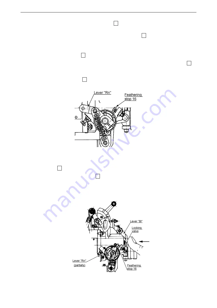
e) Loosen the stop nut on the feathering stop screw 16 (fig. 12-30]. Rotate the screw clockwise 2 to
2.5 turns. The travel of lever “Rn” (fig. 12-30) to feather position will increase.
f) Move propeller control lever easy up to the stop, which is not the stop 16 but blocking valve, to which
the pilot valve inside the governor, moved by the lever "Rn", will hit.
g) Secure propeller control lever in this position.
h) Turn counterclockwise the stop 16 and adjust it, so that exactly touching the lever "Rn" pin.
i) Loose and move propeller control lever to maximum RPM stop and turn counterclockwise the stop 16
another 0,75 ÷ 1 turn.
NOTE:
This additional turning with the stop 16 by 0,75 ÷ 1 turn ensures clearance between locking valve and the
pilot valve.
Figure 12-30 Feather stop adjustment
j) Secure the stop 16 by tightening the nut.
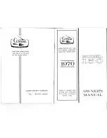
k) Move propeller control lever to the stop 16 and fix, manually through the lever "Bl" press the locking
valve according to figure 12-31. Small clearance
≈
0,1 mm (0,004 inch) must be evident.
l) Verify functionality according to section 12.7.
m) Record in the logbook.
Figure 12-31 Blocking valve clearance check
61-10-20
PROPELLER CONTROL SYSTEM
(Installation With Jihostroj LUN-Series Governor)
Page 12-32
2017-10-06


