


COMMUNICATION
Avaya 9130 1000–3000 VA UPS Site Preparation, Installation and Operator’s Manual
S
164201765 Rev 1
56
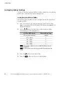
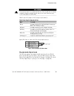
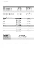
Table 6 shows the programmable settings for the signal inputs. Table 7
shows the operation logic for the signal inputs.
Table 6. Programmable Signal Inputs
Signal
Description
Not Used
The input operates only as a serial input (RxD) or has no function.
Force Bypass
If active, the UPS is forced to static bypass operation regardless of
the bypass status.
Remote Shutdown
If active, the UPS output turns off after a user-defined remote
shutdown delay. The batteries continue charging. Inactive input
does not abort the shutdown countdown and does not cause the
UPS to start up automatically.
Delayed
Shutdown
(and restart)
If active, the UPS output turns off after a user-defined delayed
shutdown delay. The batteries continue charging. Inactive input
does not abort the shutdown countdown but will cause the UPS to
start up automatically if the input voltage exists.
On Generator
If active, synchronization is disabled and the UPS transfers to
bypass.
Building Alarm 1
If active, the UPS generates the “Building Alarm 1” alarm.
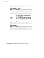
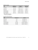
Table 7. Polarity Options
Input
Description
High
Active state on high voltage (+Udc) level
Low
Active state on low voltage (GND or -Udc) level