


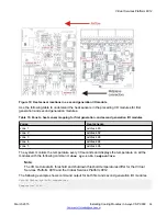

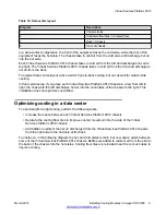
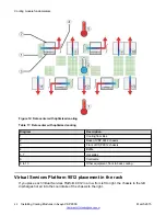


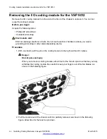


Figure 12: Data center with optimized cooling
Table 17: Data center with optimized cooling
Diagram
Description
1
Cooling floor tiles
2
Back of VSP 9012 chassis
3
Front of VSP 9012 chassis
4
Baffle
5, 7
Hot aisles
6
Cold aisle
8 to 13
Other equipment, front to back cooling
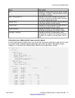
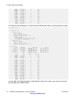
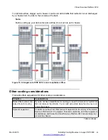
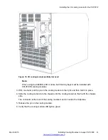
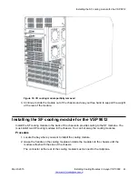
Virtual Services Platform 9012 placement in the rack
If you place each Virtual Services Platform 9012 in a row from left to right, the chassis to the left
discharges hot air into the cool intake of the chassis to the right.
Cooling module fundamentals
42
Installing Cooling Modules in Avaya VSP 9000
March 2015