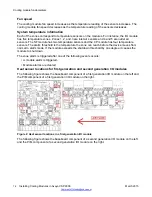


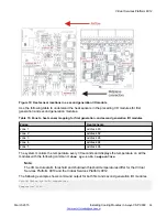

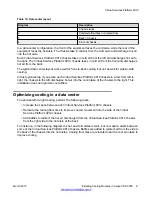
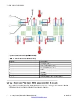

Figure 6: Front of the Virtual Services Platform 9012
Table 13: Front of the Virtual Services Platform 9012
Diagram
Description
1
I/O module air inlet
2
Power supply fan air inlet
3
I/O module air exhaust
4
9012FC or 9012FCHS cooling modules
5
Switch Fabric module air inlet
6
Airflow – left to right
Virtual Services Platform 9012
March 2015
Installing Cooling Modules in Avaya VSP 9000
29