


PID Loop Operation
Maintenance
and T
roubleshooting
8–34
PID Loop Operation
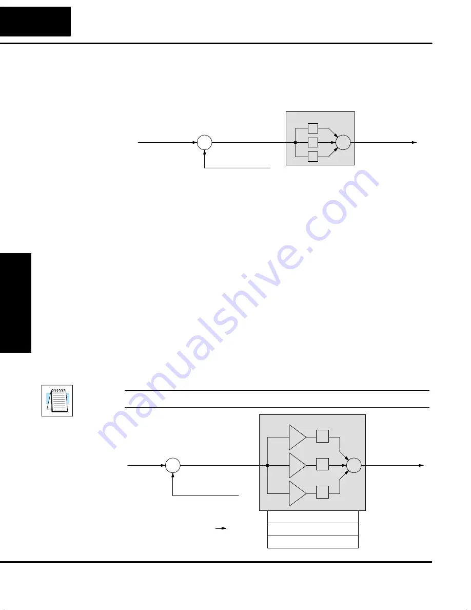
You may recall the introduction of the position and velocity forms of the PID loop
equations. The equations basically show the three components of the PID
calculation. The following figure shows a schematic form of the PID calculation, in
which the control output is the sum of the proportional, integral and derivative terms.
On each calculation of the loop, each term receives the same error signal value.
Process Variable
S
Error Term
+
–
Control Output
Setpoint
S
+
P
I
D
Loop Calculation
+
+
The role of the P, I, and D terms in the control task are as follows:
S
Proportional
– the proportional term simply responds proportionally to
the current size of the error. This loop controller calculates a
proportional term value for each PID calculation. When the error is zero,
the proportional term is also zero.
S
Integral
– the integrator (or reset) term integrates (sums) the error
values. Starting from the first PID calculation after entering Auto Mode,
the integrator keeps a running total of the error values. For the position
form of the PID equation, when the loop reaches equilibrium and there
is no error, the running total represents the constant output required to
hold the current position of the PV.
S
Derivative
– the derivative (or rate) term responds to change in the
current error value from the error used in the previous PID calculation.
Its job is to anticipate the probable growth of the error and generate a
contribution to the output in advance.
The P, I, and D terms work together as a team. To do that effectively, they will need
some additional instructions from us. The figure below shows the P, I, and D terms
contain programmable
gain
values
k
p
,
k
i
, and
k
d
respectively. The values reside in
the loop table in the locations shown. The goal of the loop tuning process (covered
later) is to derive gain values that result in good overall loop performance.
NOTE:
The proportional gain is also simply called “gain”, in PID loop terminology.
Process Variable
S
Error Term
+
–
Control Output
Setpoint
S
+
P
I
D
Loop Calculation
+
+
k
p
k
i
k
d
Loop Table
V+10
Proportional gain
XX.XX
V+11
Integral gain
XX.XX
V+12
Derivative gain
XX.XX
P-I-D Loop Terms
Summary of Contents for DL05
Page 1: ...DL05 User Manual Automationdirect com ...
Page 2: ...DL05 User Manual Automationdirect com ...
Page 436: ...1B DL05 Error Codes In This Appendix Ċ Error Code Table ...
Page 443: ...1C Instruction Execution Times In This Appendix Ċ Introduction Ċ Instruction Execution Times ...
Page 459: ...1D Special Relays In This Appendix Ċ DL05 PLC Special Relays ...
Page 464: ...1E DL05 Product Weights In This Appendix Ċ Product Weight Table ...


