background image


I.S. INTERCOM  


20-278-12 

TYPE ABMA4 USER MANUAL 

4 OF 21 

Issue: 05 


1.  GENERAL DESCRIPTION 

This document should be read in conjunction with 20-079-12 user’s manual. The intercom type ABMA4 
provides the audio communications and pre-start alarm sounding facilities of the PSACS1 system. Intercoms 
are distributed along the conveyor at fixed distances apart to provide complete sound coverage along the 
conveyor. During a pre-start sequence the intercom sounds the pre-start alarm through its two sideways 
facing speakers. These same speakers and the front panel mounted microphone are used to carry out a half 
duplex voice conversation with other intercoms on the conveyor or a surface located BMA exchange 
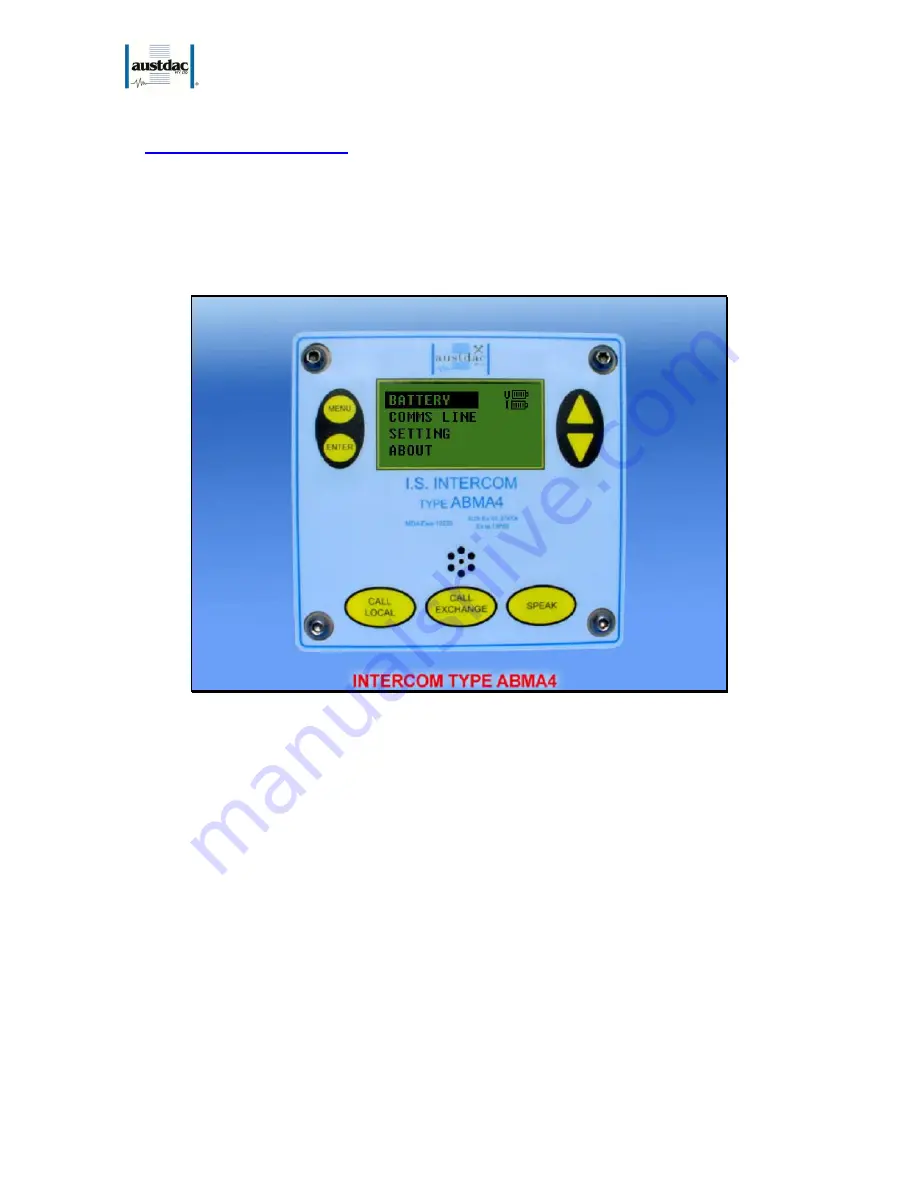
operator. Photograph 4 below shows the front panel of a type ABMA4 intercom. 


      Photograph 1: Intercom type ABMA4 front view. 


The intercom type ABMA4 has seven front panel mounted push buttons, a front panel microphone, an LCD 
display and two side-mounted speakers to provide the voice communications interface for staff working 
along the conveyor belt. The LCD display allows the operator to view operational and maintenance 
information about the intercom and the PSACS1 system. 
 
A conversation with another worker along the conveyor belt can be initiated by pressing the local call button 
once or several times. The local call button is used to signal or attract the attention of workers along the 
conveyor. The local call button can be pressed and released to sound a series of beeps along the conveyor. 
The patterns and meaning of these beeps can be used to transmit messages to others along the belt. 
The call exchange button is pressed to attract the attention of the BMA exchange operator at the surface. 
Once the operator has acknowledged the call further instructions, such as patching requests, can be given 
from the intercom. 
 
The voice communications of the PSACS1 system is a half duplex i.e. only one party can speak at a time. 
The speak button of the intercom must be pressed whenever the user wishes to speak. It is important to get 
used to pressing the speak button just before speaking and releasing it just after finishing speaking. Failure 
to control the speak button correctly will result in the beginning or end of a statement being cut off.  

Summary of Contents for ABMA4

Page 1: ...Title I S INTERCOM TYPE ABMA4 USER MANUAL Document Number 20 278 12 Issue 05 ...

Page 2: ...s the property of Austdac Pty Ltd It is subject to its recall and must not be reproduced in part or whole or its contents divulged to third parties without prior written approval from Austdac Pty Ltd TABLE OF CONTENTS TABLE OF CONTENTS 2 PHOTOGRAPHS 3 FIGURES 3 TABLES 3 1 GENERAL DESCRIPTION 4 2 OPERATIONAL DESCRIPTION 6 3 BACKGROUND OPERATIONS 6 1 Detection of PSA 6 2 Detection of Speech for Spea...

Page 3: ... View 10 Figure 6 Setting menu 10 Figure 7 Volume Menu View 11 Figure 8 Test Speaker Menu View 11 Figure 9 Test Speakers Completed View 12 Figure 10 Mute Level Menu 12 Figure 11 Password Access screen 13 Figure 12 Set Mute Level Low 13 Figure 13 Set Mute Level Medium 13 Figure 14 About Menu logo 13 Figure 15 About Menu Information 14 Figure 16 Simplified Un Shielded Circuit 14 Figure 17 TEU Fault ...

Page 4: ...along the conveyor belt The LCD display allows the operator to view operational and maintenance information about the intercom and the PSACS1 system A conversation with another worker along the conveyor belt can be initiated by pressing the local call button once or several times The local call button is used to signal or attract the attention of workers along the conveyor The local call button ca...

Page 5: ...ttery removed In the LO position the battery charge current is 11mA and 22mA in the HI position Refer to the system drawing for the correct charge rate for your intercoms Generally the HI position is used in systems with short powered segments and fewer intercoms the LO position is used in long powered segments with more intercoms Photograph 3 Battery type 5 NH 1 N side view ...

Page 6: ...at These are as follows 1 Detection of PSA Pre Start Alarm 2 Detection of Speech for Speaker Mute Control 3 Detection of Low R Line Voltage 4 Pressing of SPEAK key 5 Switching between Sleep and Deep Sleep modes 6 Watchdog kicks 1 Detection of PSA The unit continuously detects for a PSA paired tone signal on both the V line and S line The V line is the audio signal from the PSA Controller and the S...

Page 7: ...e ZERO will be displayed beneath R line Bar graph 4 Pressing of SPEAK key On pressing of the SPEAK key a press to talk PTT action the unit will wake up momentary if asleep and display SPEAK in the message text box on the Generic mode of the LCD screen The ABMA4 will turn off speakers and turn on the microphone The unit will return to sleep mode as soon as Speak key is release 5 Switching between S...

Page 8: ...state Right of the bar shows external health of interface to PSA controller The left bottom shows a message box area for display messages such as SPEAK when the SPEAK key is pressed Battery and Speaker Health Icons Icon explanation Icon Full battery and not charging Partly full battery and charging Dead battery and charging Dead battery charging fault Good Speakers low volume Good Speakers med vol...

Page 9: ...e a fault then the unit cannot see the PSA controller and will display an un tested PSA icon See System Test section below Text Box The text box area of the screen provides the user with text information referring to the operation of AMBA4 For example it displays SPEAK when the speak key is pressed or LOW LINE VOLTAGE when the R line voltage is low 5 CONFIGURATION MENU DESCRIPTION While in Generic...

Page 10: ...ine View Figure 5 gives a reading of the R line voltage and PSA loop status As in Generic mode the PSA loop shows the health of the V and S lines to the PSA controller in this menu In addition in this menu you have time and confirmation of the last PSA If Cnfrm has Y next to then directly above it will have the time in hh mm ss since the last PSA was confirmed If Cnfrm has N next to it then PSA ha...

Page 11: ...ew The Volume of the speaker output can be adjusted using the up or down keys You have three levels LOW MED and HIGH The volume icon changes depending on different volume levels The settings can be used to set the speaker volume level depending on your current position along the system cable You can exit at any time by pressing the Menu or Enter key 2 Test Speakers This Configuration Menu function...

Page 12: ...d adjust the mute level for noisy environments such as background electrical noise or RF pickup which will cause speakers to open turn on The default level is set to Low noise There is a setting below that called Clean for very electrically quiet areas and two setting above that called Med and High for noisier areas The menu is shown Figure 10 Mute Level Menu To enter a menu option eg View Mute yo...

Page 13: ...vel Low Figure 13 Set Mute Level Medium 4 About Menu The About menu show Austdac Logo and information on the product model and software version To exit either press Menu or Enter keys The following screen will be displayed Figure 14 About Menu logo After a further two second the following information will be displayed ...

Page 14: ...system components The smaller conductors are the ones that have a foil sheath in the G2000 and G2000B cables The connection of foil sheath and drain wire is critical for correct installation You must either use the shield cable correctly with the ABMA4 R Line Common line terminated with a shield drain wire at each ABMA4 or not use a shield foil drain wire at all which is the Austdac default method...

Page 15: ... a PSA Loop to confirm status to get a System Test Passed You should check that the Last PSA Confirm time is correct by going into Comms Line menu see Configuration Menu Description and Fault Analysis below If you get a PSA confirm from the controller but a ABMA4 unit doesn t show PSA Loop confirmation then fault is not in the system cable but between this cable and the unit itself i e V and S lin...

Page 16: ...nlarged PSA Loop Icon for easier readability The reasons for TEU not working are that it has been installed incorrectly the cable too long or that it is mixing with an old BMA intercom i e such as LEGACY INTERCOMS DAC TYPE STAGE II which don t have any current limiting so that if the system is heavily used the current usage goes up and line voltage drops Analysis 2 There is a break in the V line T...

Page 17: ...se as the signal may not reach the end ABMA4 unit The easiest analysis would involve just a walk down the system cable and a look at each generic display i e wakeup each unit with a menu key press to work out where the V Line tick changes to a cross Then the break will occur between these units Unfortunately because of the nature of system cable and installation history how each ABMA4 interprets t...

Page 18: ...lay will only show a PSA loop status from the last received PSA and if the V Line is cut then the ABMA4s that do not have any V Line signal do not update So they will display two ticks You must remember see fault flow diagram that a fault occurred because you did not get a confirmation from the PSA Controller You can also check the Comms Line menu see Configuration Menu section above to see when t...

Page 19: ...system OK or not The example above shows how the ABMA4 graphical display can help determine where the S Line break has occurred This method is easier to analyse than the V Line break because all ABMA4 units will have updated screens The method of detection is just a matter of walking between the TEU and PSA Controller and determining where a tick changes to a cross on the S Line As shown in the fi...

Page 20: ...ones back from the TEU will not happen You will only get a hee sound after the break and the PSA controller will not get a confirmation Again this should be your primary method of determining if the system OK or not The examples below show an enlarged R Line bar graph Icon at varying states depending on where the R line has been broken cut Figure 24 R Line break at the front Figure 25 R Line break...

Page 21: ...If you would like more accuracy reading than the bar graph 0 5 you can go into the Comms Line menu see Configuration Menu section Analysis 5 There is combination of the three above Using the graphical display on the ABAM4 you can work out which units can see a V Line an S Line and or an R M Line From this you can analyze the state of the system cable 8 HANDSET In special cases an ABMA4 can have a ...

Reviews: