


I.S. INTERCOM
20-278-12
TYPE ABMA4 USER MANUAL
10 OF 21
Issue: 05
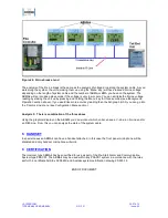
Battery Menu
This menu shows the health of battery status.
Figure 4: Battery Menu View
The figure 4 above, shows battery voltage in volts and charge current in mA units. The battery voltage
should be around 4.6 to 5.6Volts and the current between 0mA and 25mA maximum, depending on the
charge state of the battery.
To exit this menu, press either ‘Menu’ or ‘Enter’ key.
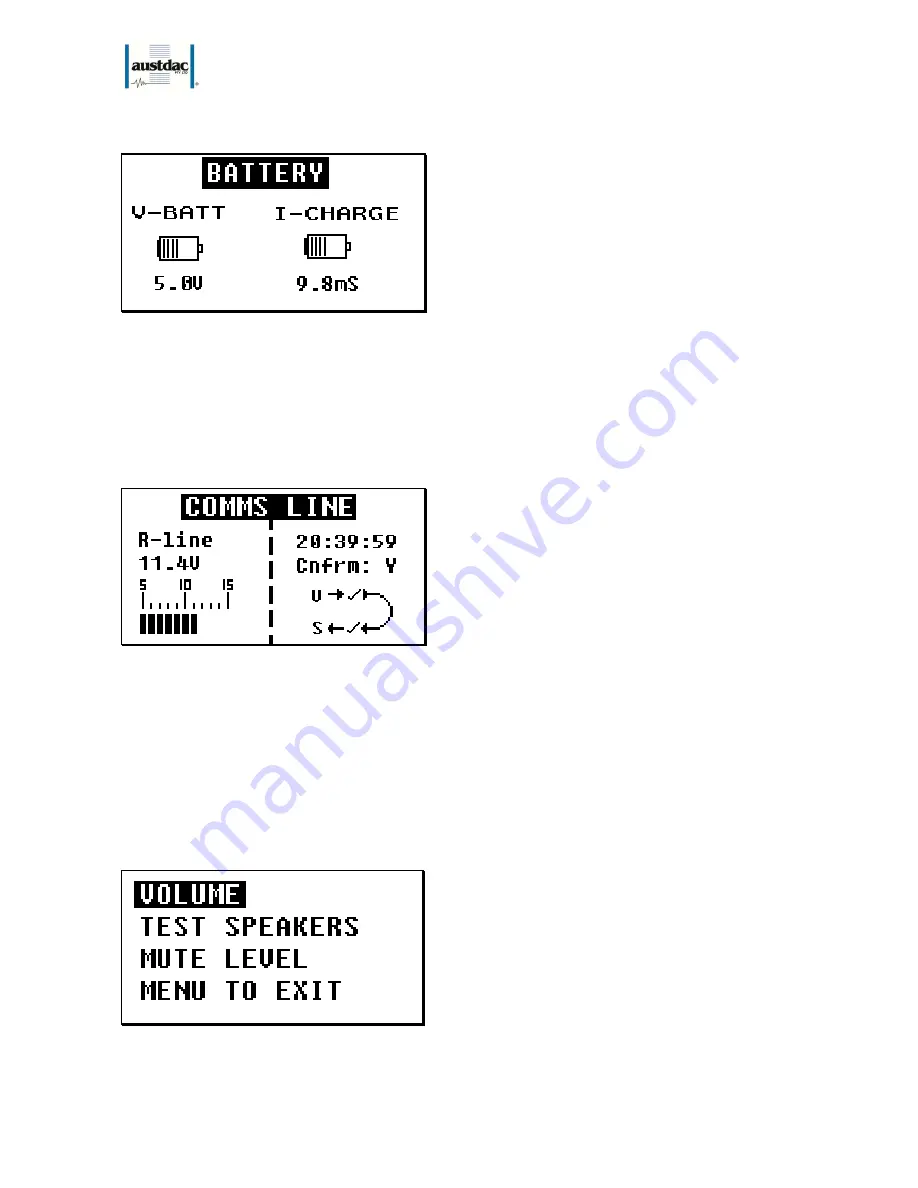
Comms Line
This menu shows the health of the interface to the PSA controller.
Figure 5: Comms Line View
Figure 5 gives a reading of the R-line voltage and PSA loop status. As in Generic mode, the PSA loop shows
the health of the V and S lines to the PSA controller in this menu. In addition, in this menu you have time and
confirmation of the last PSA. If ‘Cnfrm:’ has ‘Y’ next to, then directly above it will have the time in hh:mm:ss
since the last PSA was confirmed. If ‘Cnfrm: has ‘N’ next to it then PSA has not been confirmed and no time
will be displayed. The maximum number of hours recorded since last PSA confirm is 99hrs, which is 4 Days
and 3 hours.
To exit this menu press either ‘Menu’ or ‘Enter’ key.
Setting
This menu shows the current setting or configuration setting that can be made in the ABMA4:
Figure 6: Setting menu