


I.S. INTERCOM
20-278-12
TYPE ABMA4 USER MANUAL
3 OF 21
Issue: 05
1. Volume Option ................................................................................................................................ 11
2. Test Speakers ................................................................................................................................. 11
3. Mute Level Menu ............................................................................................................................ 12
4. About Menu .................................................................................................................................... 13
6.
INSTALLATION AND CONNECTIONS ................................................................................................ 14
Cable Shielding ................................................................................................................................... 14
7.
SYSTEM TEST AND FAULT FINDING ................................................................................................ 15
Flow Diagram Description .................................................................................................................. 15
Fault Analysis ..................................................................................................................................... 15
8.
HANDSET ............................................................................................................................................. 21
9.
CERTIFICATION .................................................................................................................................. 21
PHOTOGRAPHS
Photograph 1: Intercom type ABMA4 front view. .............................................................................................. 4
Photograph 2: Intercom type ABMA4 rear view ................................................................................................ 5
Photograph 3: Battery type 5/NH/1-N side view ................................................................................................ 5
Photograph 4: ABAM4 Menu Keys .................................................................................................................... 6
FIGURES
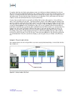
Figure 1: Confirmed PSA Loop .......................................................................................................................... 7
Figure 2: LCD Generic View .............................................................................................................................. 8
Figure 3: Menu Options ..................................................................................................................................... 9
Figure 4: Battery Menu View ........................................................................................................................... 10
Figure 5: Comms Line View............................................................................................................................. 10
Figure 6: Setting menu .................................................................................................................................... 10
Figure 7: Volume Menu View .......................................................................................................................... 11
Figure 8: Test Speaker Menu View ................................................................................................................. 11
Figure 9: Test Speakers Completed View ....................................................................................................... 12
Figure 10: Mute Level Menu ............................................................................................................................ 12
Figure 11: Password Access screen ............................................................................................................... 13
Figure 12: Set Mute Level Low ........................................................................................................................ 13
Figure 13: Set Mute Level Medium .................................................................................................................. 13
Figure 14: About Menu logo ............................................................................................................................ 13
Figure 15: About Menu Information ................................................................................................................. 14
Figure 16: Simplified Un-Shielded Circuit ........................................................................................................ 14
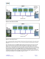
Figure 17: TEU Fault Example ........................................................................................................................ 16
Figure 18: V-Line break at the front ................................................................................................................. 16
Figure 19: V-Line break in the middle .............................................................................................................. 17
Figure 20: V-Line break at the end .................................................................................................................. 17
Figure 21: S-Line break at the front ................................................................................................................. 18
Figure 22: S-Line break in the middle .............................................................................................................. 19
Figure 23: S-Line break at the end .................................................................................................................. 19
Figure 24: R-Line break at the front ................................................................................................................. 20
Figure 25: R-Line break in middle ................................................................................................................... 20
Figure 26: R-Line break at end ...................................................................................................................... 211
TABLES
Table 1: Top Left Generic Icons ........................................................................................................................ 8
Table 2: Top Right Generic Icons ...................................................................................................................... 9