I.S. INTERCOM
20-278-12
TYPE ABMA4 USER MANUAL
14 OF 21
Issue: 05
Figure 15: About Menu Information
6. INSTALLATION AND CONNECTIONS
Cable Shielding
From “PRE-START ALARM AND COMMUNICATIONS SYSTEM TYPE PSACS1” user manual (20-079-12)
the following system cables are used: G2000 and G2000B both have a foil and drain wire and cable CABL25
has no shielding at all. The cable is a very important part in the system as it carries all the signals and
distributes power to all the system components. Of the conductors, two are larger in cross sectional area
than the other two. The two larger cross sectional area conductors are used to distribute power to the system
components while the smaller conductors are used to convey signals between the various system
components. The smaller conductors are the ones that have a foil sheath in the G2000 and G2000B cables.
The connection of foil sheath and drain wire is critical for correct installation. You must either use the shield
cable correctly with the ABMA4 R-Line (Common line) terminated with a shield drain wire at each ABMA4 or
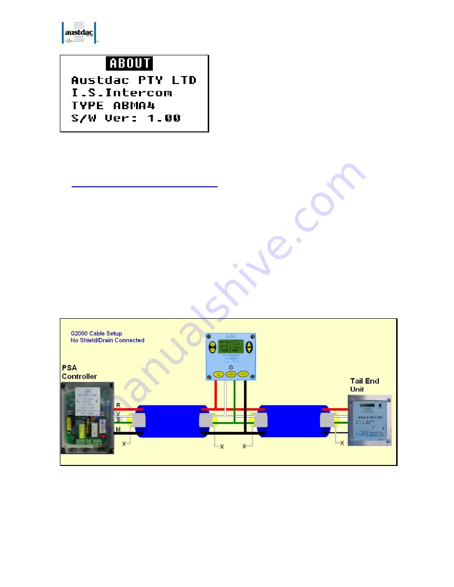
not use a shield foil/drain wire at all, which is the Austdac default method. The shield is not passed through
and is left floating as depicted in the electrically simplified figure 16 below:
Figure 16: Simplified Un-Shielded Circuit
If the shield is passed through from one cable to another between ABMA4 terminations and is not terminated
at the R-Line then this is electrically noisier than having no shield at all. The coupling between shield and the
V and S cores has the effect of giving alternative PSA signal paths that can cause the PSA Controller and
ABMA4s to receive false confirmations on tail end units.


