Aulisa Guardian Angel Rx Guardian Angel Rx Lite GA2000 Series Instructions For Use Manual Download Page 40

39 


Step 3:


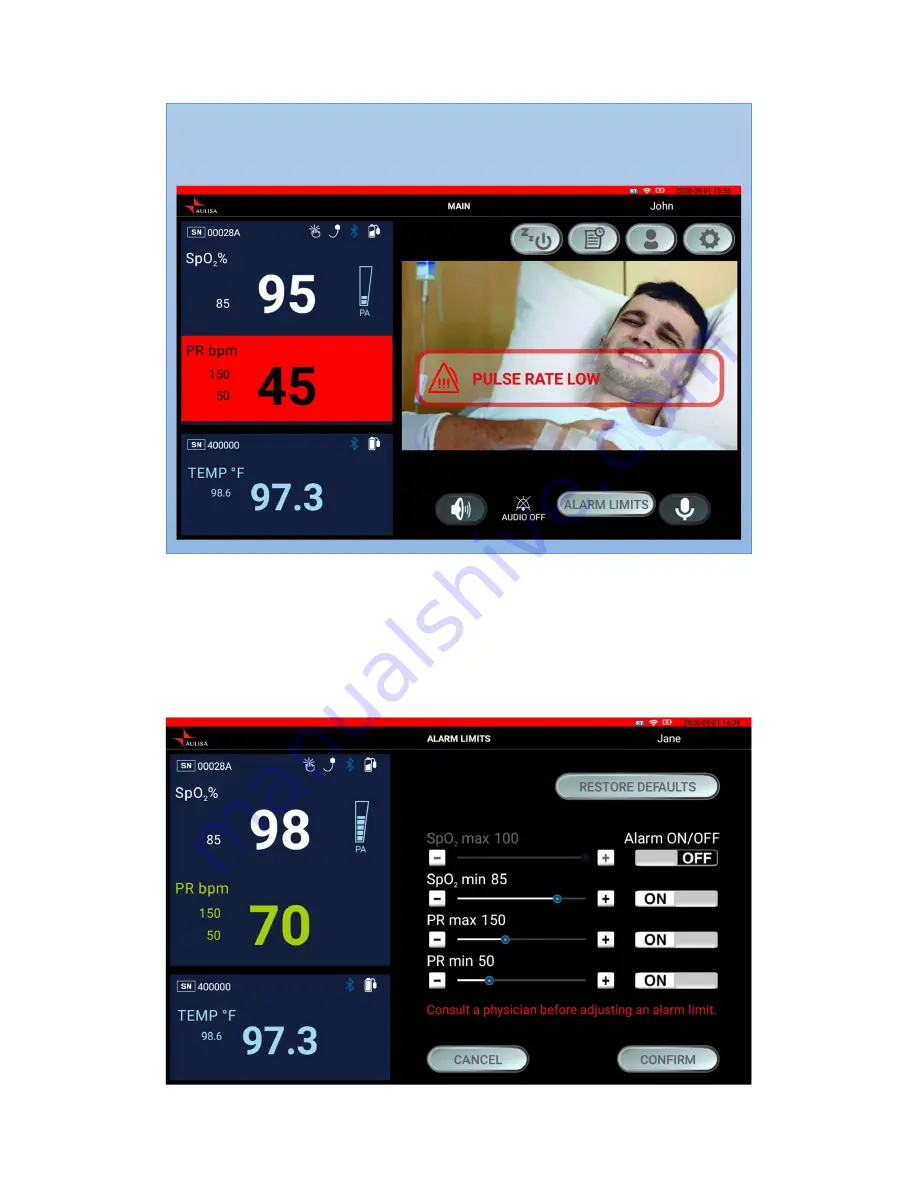
To turn alarms on or off, tap on ʻʻON/OFFʼʼ button. (Turn on the alarm before 
adjusting the value.) 

Step 4:


Tap on ʻʻ + ʼʼ or ʻʻ– ʼʼ buttons or drag the ʻʻseekbarʼʼ to adjust the values OR 
tap on “RESTORE DEFAULTS” to restore alarm limits to manufacturer 
configured values. 


NOTE: 

Alarm limits can be adjusted only when the Aulisa sensor module(s) is paired. 

NOTE: 

In an alarm event, ʻʻALARM LIMITSʼʼ button will appear after you select "AUDIO 

PAUSE" button or "AUDIO OFF" button. 


Summary of Contents for Guardian Angel Rx Guardian Angel Rx Lite GA2000 Series

Page 1: ...Digital Vital Sign Monitoring System Instructions For Use ____________________________________________________________ 7MN00022 02 Guardian Angel Rx Guardian Angel Rx Lite GA2000 Series...

Page 2: ...l imply Taiwan Aulisa Medical Devices Technologies Inc Aulisa is a registered trademark of Taiwan Aulisa Medical Devices Technologies Inc Taiwan Aulisa Medical Devices Technologies Inc No 218 2 Chong...

Page 3: ...Fi Network Initial Setup 26 Wi Fi Network Reset 27 Device Pairing 28 Automatic Pairing Guardian Angel Rx only 28 Pairing with a new Aulisa sensor module 28 Pairing with a new Receiver Transponder 29...

Page 4: ...3 FCC Compliance 48 Service Support and Warranty 50 Specifications 51 Parts and Accessories 53...

Page 5: ...4 Guide to Symbols Single Use MR Unsafe must not be used in an MRI environment...

Page 6: ...5 Date of Manufacture...

Page 7: ...ical or physiological events Aulisa mobile application The Aulisa mobile application can be installed on your mobile device as the display of the system to replace the Display Unit Please download Aul...

Page 8: ...e Sensor Patch The Thermometer Box is embedded with a Bluetooth module and powered by a changeable button cell battery It is intended for adults pediatrics and infants GA2000 Series Function The Aulis...

Page 9: ...onments This system is a reusable device The Infant Oximeter Module is indicated for spot checking and or continuous monitoring of SpO2 and PR of pediatrics and infants during non motion and under wel...

Page 10: ...e in measuring recording and displaying functional oxygen saturation of arterial hemoglobin SpO2 and pulse rate PR and body temperature The intended environments of use are hospitals medical facilitie...

Page 11: ...d 8 Only use this device with charging adaptors provided by Aulisa 9 Do not immerse any part of the device in any liquids 10 Do not subject the device to extreme hot or cold temperatures humidity or d...

Page 12: ...data transfer Alarm notifications will be triggered for such failure 15 It is recommended that the system works on an independent Wi Fi network and always use the Wi Fi network with WPA2 PSK security...

Page 13: ...a mobile application Aulisa Lite GA1000 Smartphone not included Receiver Transponder Display Unit Stand Display Unit Charging Adapter Type C Receiver Transponder Charging Adapter Receiver Transponder...

Page 14: ...serves as a substitute for the Display Unit when installed on personal mobile devices Please download Aulisa Lite GA1000 from App Store or Google Play Below table introduces the interface of the Auli...

Page 15: ...er a serial number of Aulisa sensor module s either by scanning the QR code or by key in the number manually Alarm Setting Adjust the alarm upper limit and lower limit of each parameter User Profile F...

Page 16: ...lay Unit Icon Name Description SpO2 Blood oxygen Blood oxygen saturation PR bpm Pulse rate Pulse rate beats per minute TEMP Body temperature Body temperature in either C or F Pulse amplitude PA Pulse...

Page 17: ...indicates whether the oximeter sensor cable is connected to the oximeter box A system alarm will be displayed if the cable is disconnected Measurement Site Status This icon indicates whether the Infan...

Page 18: ...ction Wi Fi Strength Indicator This icon indicates whether there is a strong connection for the customer Wi Fi Network Alarm Indicator This icon identifies an alarm condition exists represents high pr...

Page 19: ...nction Press and hold this button on the MAIN screen to talk to the person being monitored Listening Function Tap on this button on the MAIN screen to receive audio of person being monitored via the R...

Page 20: ...ure configured values Establish Pairing In the Setting menu tap on this button to pair to a new Aulisa sensor module or Receiver Transponder either by scanning the barcode or manually keying in the co...

Page 21: ...20 Standby The button appears when the Infant Oximeter Module is detached from the foot Tap on the button to return to the Before You Start page STANDBY...

Page 22: ...tal signs monitoring data from the Aulisa sensor module s via Bluetooth integrates audio and video of the person being monitored and then converts the data to Wi Fi signals which are transmitted to an...

Page 23: ...22 Audio Video Feature Video View monitoring video Listening Tap to turn on and receive monitoring audio Talking Press and hold to send an audio message...

Page 24: ...Connect the charging adaptor to the Receiver Transponder and a power outlet Step 2 You may simply place the Receiver Transponder on a table or follow the instructions below to assemble the holder and...

Page 25: ...he wall c Ensure the Holder is secure Place the Receiver Transponder body on the Holder d Secure the power cable to the Holder with Velcro strap NOTE Securing the power cable to the holder with the Ve...

Page 26: ...mation will appear on the MAIN screen NOTE The power LED will light green when the power is on CAUTION It is recommended to keep your mobile device plugged in when using Aulisa mobile application on y...

Page 27: ...curity password and press CONFIRM Step 5 Create a password for the Receiver Transponder and press CONFIRM Step 6 Select the correct time zone and press CONFIRM for Display Unit only NOTE Beware of con...

Page 28: ...displayed on the Display Unit Aulisa mobile application for Android user or key in the network name for iOS user Enter the network security password and press CONFIRM Step 4 Create a password for the...

Page 29: ...ONFIRM if the serial number SN displayed matches with the one on the Aulisa sensor module s Step 5 To confirm that the process was successful ensure that the Bluetooth NOTE The Aulisa sensor module s...

Page 30: ...tton of Receiver Transponder for 10 seconds until RESET is heard Wait for 1 minute until the Receiver Transponder plays a melody to proceed to the next step b Select the desired Wi Fi network from the...

Page 31: ...nsecured network provides no security and exposes all your network traffic NOTE Ensure the customer Wi Fi Network connection has a strong and reliable signal NOTE The Wi Fi Link LED on Receiver Transp...

Page 32: ...or module s Instructions for Use for setting up instructions Step 2 Ensure the Bluetooth and Wi Fi connections are established respectively See Device Connection and Device Pairing sections Step 3 Set...

Page 33: ...with the charging adaptor ALWAYS plugged in If the Display Unit has been disconnected from the charging adaptor proceed with the following steps to charge and power the Display Unit The Display Unit w...

Page 34: ...p 2 Attach the wall adaptor to a power outlet NOTE The AC power LED indicator lights green when AC adaptor is plugged in NOTE The charging LED indicator lights blue during charging and goes off when f...

Page 35: ...e that require immediate attention to the person being monitored including SpO2 pulse rate and temperature alarms On the screen high priority alarms are indicated with rapid blinking vital sign readin...

Page 36: ...alarm audio for 2 minutes Tap on AUDIO OFF button to permanently silence the alarm audio See Alarm Limits section for adjusting the alarm limit Medium Priority Alarms Medium priority alarms are those...

Page 37: ...ual Indicator Oximeter Sensor Probe Detached from the Finger 1 Alarm text message in yellow blinks rapidly on the screen 2 Alarm LED indicator on the Oximeter Module blinks yellow Oximeter Sensor Cabl...

Page 38: ...has been resolved CAUTION Tapping on AUDIO OFF button will permanently silence the alarm audio of the current triggering alarm event CAUTION A potential hazard exists if different alarm presets are u...

Page 39: ...et alarm limits Step 1 Ensure the system connection Bluetooth Wi Fi is established See Device Connection and Device Pairing sections Step 2 Tap on SETTING button on the MAIN screen and then tap on ALA...

Page 40: ...ons or drag the seekbar to adjust the values OR tap on RESTORE DEFAULTS to restore alarm limits to manufacturer configured values NOTE Alarm limits can be adjusted only when the Aulisa sensor module s...

Page 41: ...before adjusting the alarm limits CAUTION A potential hazard exists if different alarm presets are used for the same or similar equipment in any single area CAUTION When turned off the alarms will no...

Page 42: ...ls High Priority Alarm Factory Default Adjustment Options Adjustment Interval SpO2 Upper Alarm Limit Off Off 85 100 1 SpO2 Lower Alarm Limit 85 Off 50 95 1 Pulse Rate Upper Alarm Limit Adult Pediatric...

Page 43: ...s not possible Do not attempt to open the case Opening the Display Unit or Receiver Transponder will cause damage and void the warranty If the Display Unit or Receiver Transponder is not functioning p...

Page 44: ...rm mode but no audible alarms can be heard 1 Wait for two 2 minutes and alarm tones will automatically re engage 2 Make sure no headphone is plugged in Cannot establish system connection 1 Make sure t...

Page 45: ...ment Emissions test Compliance Electromagnetic environment guidance RF emissions CISPR 11 Group 1 This device uses RF energy only for its internal function Therefore its RF emissions are very low and...

Page 46: ...hat of a typical commercial or hospital environment Surge IEC 61000 4 5 1 kV Line to Line 1 kV Line to Line Mains power quality should be that of a typical commercial or hospital environment Voltage d...

Page 47: ...y an electromagnetic site survey a should be less than the compliance level in each frequency range b Interference may occur in the vicinity of equipment marked with the following symbol Radiated RF I...

Page 48: ...47 abnormal performance is observed additional measures may be necessary such as reorienting or relocating thedevice b Over the frequency range 150 kHz to 80 MHz fieldstrengths should be less than 3 V...

Page 49: ...relocate the receiving antenna 2 Increase the separation between the equipment and receiver 3 Connect the equipment into an outlet on a circuit different from that to which the receiver is connected 4...

Page 50: ...equires this product to be used indoors for the frequency range of 5 15 to 5 25GHz to reduce the potential for harmful interference to co channel mobile satellite systems High power radar is allocated...

Page 51: ...ii purchaser has returned the product to Aulisa in accordance with instructions provided on Aulisa s support webpage and iii Aulisa has verified that the product is defective Aulisa warrants a replac...

Page 52: ...ressure 60dB Ingress Protection IP22 Receiver Transponder Power Requirements Mains 100 240V AC 50 60 Hz DC Input 5V DC AC adaptor Internal Power Battery Type 3 7V battery Battery Life 2 hours of conti...

Page 53: ...otocol 802 11 b g n ac 2 4GHz 5GHz Direction Bi direction Classifications per IEC 60601 1 Type of Protection Class II MOPP on AC power Internally powered on battery power Type of Protection Type BF Ap...

Page 54: ...dian Angel Rx only Refer to the Aulisa sensor module s Instructions for Use for more Aulisa sensor module s information You may also contact your distributor or contact Aulisa by going online at www a...

Reviews: