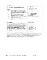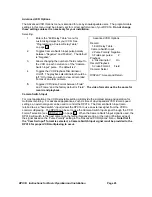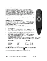
DPX16: Instructions for Basic Operation and Installation
Page 6
3.
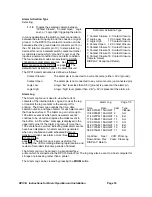
Determine the record speed (record hours format) you will use with your VCR and set up
the DPX16 to work with your VCR using the “VCR Set up” and “VCR Selection” menus
(see page 10).
4.
Exit the DPX16 menus by pressing the DISPLAY button to exit each menu and finally the
menu system.
5.
If your VCR has internal “on-screen” menus for its set up, use the “VCR Bypass” feature
of the DPX16 (see the “VCR Bypass Operation” description on page 8) to view the VCR’s
“on-screen” menus on the display monitor.
6.
At this point, the basic configuration of your DPX16 is complete. You may now proceed to
set more advanced functions as required for your installation (alarms, camera labels,
multiplexing options, etc.). Refer to the “Advanced Function Menus” starting on page 11
for detailed information for the feature(s) you require.
R
EAR
P
ANEL
C
ONNECTIONS
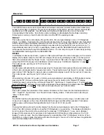
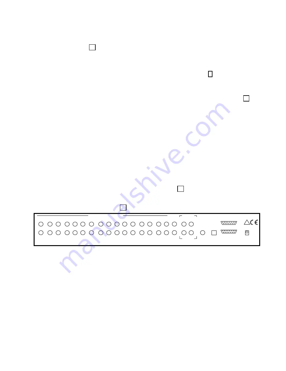
The sixteen camera input BNC connectors each have a looping output and the factory default
configuration of each 75 Ohm termination is ON. Eight DIP switches inside the unit (see section below)
determine whether the termination is ON or OFF for each camera input.
The DPX16 has both Composite (BNC) and S-Video (DIN) outputs for the main color monitor. For
optimum resolution, it is recommended that you use the S-Video cable to connect to the S-Video input on
your color monitor. If this input is available on your monitor, it may also be called the “S-VHS” or “Y/C”
input.
Connect a cable from the “VCR IN” BNC (or S-Video connector) to the video output of the VCR and a
cable from the “VCR OUT” BNC (or S-Video connector) to the video input of the VCR. You must use
either
the Composite video connection (BNC) or the S-Video (DIN) connection. In order for your DPX16 to
work properly with the VCR, DO NOT CONNECT CABLES FROM THE VCR TO BOTH THE BNC AND
S-VIDEO DIN CONNECTORS. Once you have connected the VCR, you must choose either the
“Composite” or “S-Video” mode in the “VCR Set-up Menu” (see page 10). The factory default is
“Composite”. It is also recommended that you use the S-Video connections on your VCR.
The two alarm connectors are a standard DB-15 type that will mate with the alarm wire adapter board or a
standard computer-type cable. See page 24 for further alarm connection information.
1
8
9
15
REAR PANEL
16
15
14
13
12
11
10
9
8
7
6
5
4
3
2
1
MAIN
VCR
OUT
VCR
IN
S-VIDEO
MONITOR
SERIAL
PORT
ALARMS 10 - 16
ALARMS 1 - 9
POWER
12 ~ VAC
2.0 AMP
MADE IN U.S.A.
1
8
9
15
CALL
!
T
OP
C
OVER
R
EMOVAL
The top cover of the DPX16 should only be removed if it is necessary to adjust input termination settings,
or RS-232 port settings. To remove the top cover, remove the 4 screws on each side. Gently slide the
top cover back until the cover disengages from the plastic front panel bezel and then lift the cover off the
chassis. DO NOT ATTEMPT TO PULL THE COVER DIRECTLY UPWARD WITHOUT DISENGAGING
IT FROM THE FRONT BEZEL.
V
IDEO
L
INE
T
ERMINATION
S
WITCHES
The video line termination switches for each camera input are accessed by removing the top cover. The
switches are located in pairs near the back panel on the main circuit board. Each switch pair is marked on
the circuit board and the 75 Ohm termination is enabled when the switch is in the “ON” position. The
factory default setting for each input is 75 Ohm termination “ON”. Also note that there is an additional
termination switch for the VCR input.


