background image

ATAB5749 [APPLICATION NOTE]

9138B–AUTO–07/15

12

Telegram:
The following parameters of the telegram to be transmitted can be determined in this menu:

Data rate can be set between 0.5Kbit/s to 40Kbit/s in 1Kbit/s step

Preburst can be defined between 8 bits to 1000 bits in 8 bit step

Testword is the data content of the telegram up to 4 data bytes length.

Note:

All the information in this menu is based on the Manchester coding scheme.

Programmable Push Buttons:

This section lists the possible functions of the three buttons on board:

Single telegram

Continuous telegram

Single pattern

Continuous pattern

Continuous preburst

Continuous carrier (unmodulated)

Pattern:

For the pattern, the following parameters can be set: 

Data rate can be set between 0.5Kbit/s to 40Kbit/s in 1Kbit/s step,

Pattern length can be set between 8 bits to 256 bits in 8 bits step

Pattern data

Note:

The construction of the Pattern consist only of the determined bits due to the configuration of the Pattern menu, 
so without Preburst the pattern configuration is not Manchester coded.

Application:

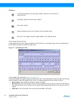
If this menu is selected, a simple illustration of the application circuit of the ATA5749 is displayed (see 

Figure 2-10

).

Figure 2-10. The Simple Application Circuit Shown in the RF Design Kit Software 

After programming the parameters, the transmitter board can be unplugged from the interface on the microprocessor 
board.

Insert the lithium cell into the battery holder of the transmitter board.

The transmitter board is ready for verification.

Summary of Contents for ATAB5749

Page 1: ...Atmel s newest UHF transmitter boasts many new features The main new feature is its programability Parameters such as transmit power the transmit frequency and the frequency deviation for FSK modulati...

Page 2: ...on the board for programming An external microcontroller can be used to set the ATA5749 on the boards since some test points are placed on the control and the programming traces of ATA5749 Note The co...

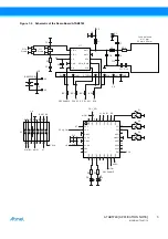
Page 3: ...8 7 2 1 4 3 GND3 GND5 PB7 PB6 VCC6 VCC4 PD4 PD3 PB4 PB3 PB2 PD7 PD6 PD5 11 12 9 10 15 16 13 14 30 29 32 31 26 25 28 27 PB0 PB1 PC2 PC3 PC4 PD0 PD1 PD2 PC6 PC5 CLK 10 1 ANT2 U1 BA2032SM C1 C8 C7 C9 C1...

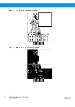
Page 4: ...ATAB5749 APPLICATION NOTE 9138B AUTO 07 15 4 Figure 1 3 Top Layer of the Demo Board ATAB5749 Figure 1 4 Bottom Layer of the Demo Board ATAB5749...

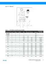
Page 5: ...0603 C1 1 x x 100nF 10 X7R 0603 Murata C2 C3 2 x x 15pF 2 COG 0603 Murata C5 1 x x 68nF 10 X7R 0603 Murata C6 1 x x 1nF 10 X7R 0603 Murata C7 n m C8 1 x 3 9pF 5 COG 0603 Murata 1 x 18pF 5 COG 0603 Mu...

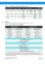
Page 6: ...Material of the Demo Board ATAB5749 Continued Components Pieces 315MHz 433MHz Value Tolerance Material Housing Manufacturer Distributor Table 1 2 Software Default Settings of the ATAB5749 ATA5749 433...

Page 7: ...th a 12V power supply Switch on the 12V DC power supply of the microprocessor board before running the RF design Kit software The file RF Designkit exe runs the software and test the connection to the...

Page 8: ...ated in Figure 2 3 Figure 2 3 Error Code for Removing the Battery during the Programming Process Plug the transmitter board into the socket on the microprocessor board The RF transmitter type and the...

Page 9: ...drop down menu see Figure 2 5 Figure 2 5 Transmitter Section by the Corresponding Part Number After selecting the correct transmitter in this case the ATA5749 315MHz or ATA5749 433MHz a menu of param...

Page 10: ...a The following parameters of the ATA5749 can be set Band Selection either 300MHz to 368MHz or 367MHz to 450MHz RF Frequency The transmit frequency of the board can be determined by selecting the valu...

Page 11: ...Clock Only Mode in this menu Clock Only Mode or Normal Mode can be chosen With Clock Only Mode the ATA5749 generates a clock signal based on the crystal frequency for the microcontroller and no transm...

Page 12: ...Pattern For the pattern the following parameters can be set Data rate can be set between 0 5Kbit s to 40Kbit s in 1Kbit s step Pattern length can be set between 8 bits to 256 bits in 8 bits step Patt...

Page 13: ...R7 1k on the transmitter interface board must be replaced with 0 resistor Refer to Figure 3 1 for the position of the R7 A grey jack is generally delivered with the older version of the Atmel transmi...

Page 14: ...NT EVEN IF ATMEL HAS BEEN ADVISED OF THE POSSIBILITY OF SUCH DAMAGES Atmel makes no representations or warranties with respect to the accuracy or completeness of the contents of this document and rese...

Page 15: ...Mouser Electronics Authorized Distributor Click to View Pricing Inventory Delivery Lifecycle Information Microchip ATAB5749 3 ATAB5749 4...

Reviews: