ATAB5749 [APPLICATION NOTE]
9138B–AUTO–07/15
10
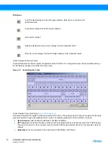
TX Buttons:
Control Register Table (CR-Table):
This table illustrates the internal register configuration of the ATA5749. The configuration bytes can be modified directly in
the CR-Table by clicking in the field of the binary value.
Figure 2-7.
Control Register Table
Control Register Value (CR-Value) (
):
This window interprets the register configuration setting of CR-Table. If the setting in the CR-Table is changed, the CR-Value
window shows the change automatically and vice versa. The following parameters of the ATA5749 can be set:
●
Band Selection:
either 300MHz to 368MHz or 367MHz to 450MHz.
●
RF Frequency:
The transmit frequency of the board can be determined by selecting the value of the FREQ register.
The
green check mark
in the drop down menu shows the FREQ values allowed; the
red cross
shows the values not
allowed.
●
Modulation:
sets the modulation of the board either to ASK Mode or FSK Mode
Load TX default settings into the RF design software. Note: this is not stored on the
transmitter board.
Load custom settings into the RF design software.
Save custom settings.
Read and display the whole current settings from the transmitter board.
Write the current settings from the RF Design software to the transmitter board.

