


AT-OME-TX21-WP-E
9
AT-OME-TX21-WP-E
HDMI
USB-C
INPUT
USB-C LINK
HDMI PWR AUTO
OMEGA
TM
RESET
IP
TEST
FW
AT-OME-TX21-WP-E
HDMI
USB-C
INPUT
USB-C LINK
HDMI PWR AUTO
OMEGA
TM
RESET
IP
TEST
FW
AT-OME-TX21-WP-E
HDMI
USB-C
INPUT
USB-C LINK
HDMI PWR AUTO
OMEGA
TM
RESET
IP
TEST
FW
5
6
7
3
2
1
4
8
9
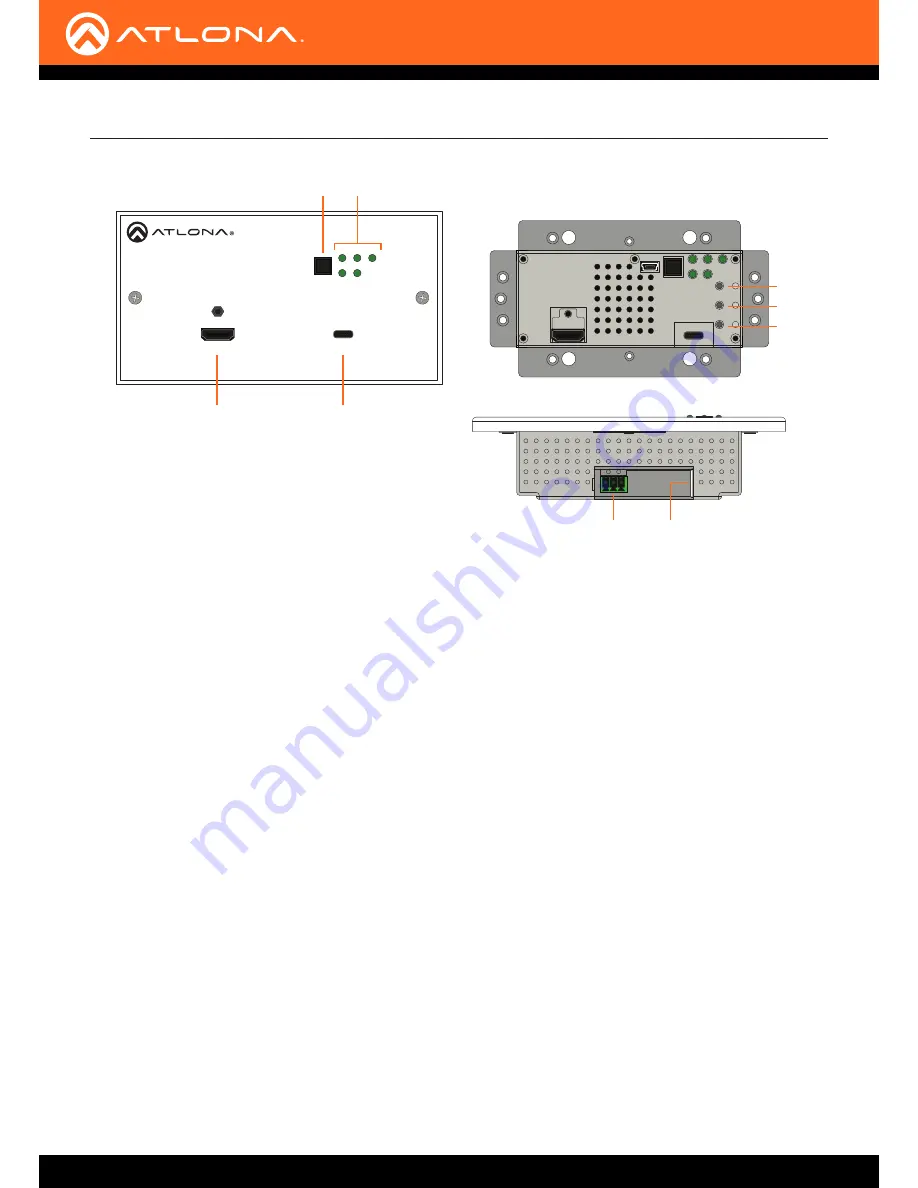
Front (shown with EU wallplate attached)
Front (shown with wallplate removed)
Bottom
Panel Description
1 HDMI
Connect an HDMI cable from this port to an HD/UHD
source.
2 INPUT
Press and release this button to manually switch
between
HDMI
and
USB-C
inputs.
3 LED Indicators
Indicators for power, active source, auto-switch
mode, and link integrity.
HDMI
This LED indicator glows solid green when a source
is connected to the
HDMI
port.
PWR
This LED indicator glows solid green when the unit is
powered using a PSE-series receiver.
AUTO
This LED indicator glows solid green when auto-
switch is enabled.
USB-C
This LED indicator glows solid green when the
USB-C port is the active input.
LINK
This LED indicator glows solid green when the link
integrity between the unit and a receiver is good.
4 USB-C
Connect a USB-C cable from a video source to this
input. This port does not support data or charging of
external devices.
5 RESET
Press and hold this button for 10 seconds to reset the
unit to factory-default settings.
6 IP
Press and hold this for approximately 5 seconds to
set the IP mode. Refer to
IP Configuration (page
15)
for more information.
7 TEST
This button is reserved for future expansion.
8 RS-232
Connect an RS-232 cable, with a 3-pin captive
screw connector, from this port to a control system.
Refer to
RS-232 Connector (page 10)
for more
information.
9 HDBaseT OUT
Connect an Ethernet cable from this port to a locally-
powered HDBaseT receiver such as the AT-HDVS-
200-RX, AT-HDVS-150-RX, or AT-UHD-EX-100CE-
RX-PSE.


