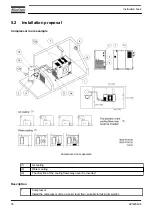
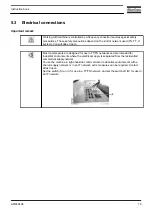
2
Position of the compressed air outlet valve.
3
The pressure drop over the air delivery pipe can be calculated from:
Δp = (L x 450 x Q
c
1.85
) / (d
5
x P), with
d = inner diameter of the pipe in mm
Δp = pressure drop in bar (recommended maximum: 0.1 bar (1.5 psi))
L = length of the pipe in m
P = absolute pressure at the compressor outlet in bar(a)
Q
c
= free air delivery of the compressor in l/s
It is recommended that the connection of the compressor air outlet pipe is made on top of the
main air net pipe in order to minimize carry-over of possible condensate residue.
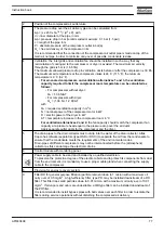
4
Ventilation: the inlet grids and ventilation fan should be installed in such a way that any
recirculation of cooling air to the compressor or dryer is avoided. The maximum air velocity
through the grids is 5 m/s (16.5 ft/s).
The maximum allowed pressure drop in ventilation ducts before or after the compressor is 30 Pa.
The maximum air temperature at the compressor intake is 46 ˚C (115 ˚F), the minimum
temperature is 0 ˚C (32 ˚F).
•
For air-cooled compressors and ventilation alternatives 1 and 3, the ventilation
capacity required to limit the compressor room temperature can be calculated as
follows:
• For compressors without dryer:
Q
v
= 1.06 N/ΔT
• For compressors with dryer:
Q
v
= (1.06 N + 1.2 D)/ΔT
with
Q
v
= required ventilation capacity in m
3
/s
N = nominal power of the compressor motor in kW
D = electric power of the dryer in kW
ΔT = temperature increase in the compressor room in °C
For ventilation alternatives 2 and 4:
the fan capacity should match the compressor fan
capacity at a pressure head equal to the pressure drop over the air ducts.
Apply separate outlet ducts for the compressor and the dryer.
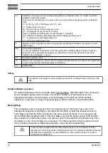
5
The drain pipes to the drain collector must not dip into the water of the drain collector. Atlas
Copco has oil/water separators (type OSD or OSCi) to separate the oil from the condensate to
ensure that the condensate meets the requirements of the environmental codes.
Drain pipes of different compressors may not be interconnected before the (atmospheric)
collector as this can damage the electronic drains.
6
Control module with monitoring panel.
7
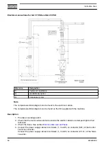
Power supply cable to be sized and installed by a qualified electrician.
To preserve the protection degree of the electric cubicle and to protect its components from dust
from the environment, it is mandatory to use a proper cable gland when connecting the supply
cable to the compressor.
8
Provision for energy recovery system.
9
Filter DD for general purpose filtration (particle removal down to 1 micron with a maximum oil
carry over of 0.5 mg/m
3
. A high-efficiency filter, type PD, may be installed downstream of a DD
filter. This filter traps solid particles down to 0.01 micron with a maximum oil carry-over of 0.01
mg/m
3
. If oil vapors and odors are undesirable, a QD type filter can be installed downstream of
the PD filter.
It is recommended to install bypass pipes with ball valves over each filter in order to isolate the
filters during service operations without disturbing the compressed air delivery.
Instruction book
API480496
77
Summary of Contents for GA 37 VSD
Page 1: ...INSTRUCTION BOOK API480496 GA 37 VSD ...
Page 2: ......
Page 14: ...Front view GA 37 VSD up to GA 45 VSD Workplace Full Feature Instruction book 12 API480496 ...
Page 127: ......


