4
F_7.1_0
1_US.
fm 4-
8
Planetary gear (2)
Care must be taken to ensure fluids are contained
during performance of inspection, maintenance,
testing, adjusting and repair of the paver. Be pre-
pared to collect the fluid with suitable containers
before opening any compartment or disassembling
any component containing fluids. Always dispose
of fluids according to local regulations and man-
dates.
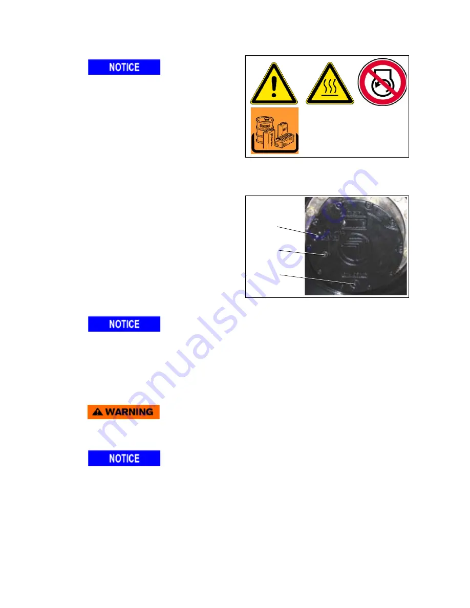
To check the oil level in the Planetary Gearbox
- Position the planetary gearbox so that the oil
drain (B) is vertical at its lowest point (about
the 6 o’clock position). The oil filler plug (C)
should then be on the Left or Right outside fo
the planetary middle.
- Clean the area around the check and fill
plugs and the drain plug.
- Place an oil collection container underneath
the planetary gearbox.
The proper oil level is at the lower edge of the inspection port (A) or a little oil flows from the hole.
- Remove the oil level check plug (A). The oil level should be at the oil level check port.
- If the level is low, add oil.
Gearbox must be filled with fresh, clean oil.
If the oil looks contaminated, it must be drained and replaced with clean, fresh oil.
- Fill with oil until the level has reached the oil level check port (A). Insert check and fill plugs and then
tighten
B
A
C
Summary of Contents for Dynapac F1000W T4i
Page 2: ...www atlascopco com...
Page 18: ...V 10 V_01_US fm...
Page 20: ......
Page 42: ...4 C_1 1_01_US fm 4 16 Transport on Low Bed Trailers 1 7 10 4 11 5 8 2 9 12...
Page 47: ...9 C_1 1_01_US fm 9 16 Transport Preparation 7 4 5 11 9 2 8 10 1 12...
Page 49: ...11 C_1 1_01_US fm 11 16 3 2 Driving mode 3 1 2...
Page 66: ...D 1 1 12 D_1 1_01_US fm 12 44 PANEL C 46 45 47 48 43 44 41 42 40 49...
Page 68: ...D 1 1 14 D_1 1_01_US fm 14 44 PANEL C 46 45 47 48 43 44 41 42 40 49...
Page 70: ...D 1 1 16 D_1 1_01_US fm 16 44 PANEL C 46 45 47 48 43 44 41 42 40 49...
Page 72: ...D 1 1 18 D_1 1_01_US fm 18 44 PANEL D 53 54 55 51 50 52 53 52 51 50...
Page 74: ...D 1 1 20 D_1 1_01_US fm 20 44 PANEL D 53 54 55 51 50 52 53 52 51 50...
Page 76: ...D 1 1 22 D_1 1_01_US fm 22 44 PANEL D 53 54 55 51 50 52 53 52 51 50...
Page 78: ...D 1 1 24 D_1 1_01_US fm 24 44 PANEL E 56 57 58...
Page 80: ...D 1 1 26 D_1 1_01_US fm 26 44 PANEL E 56 57 58...
Page 82: ...D 1 1 28 D_1 1_01_US fm 28 44 3 Auxiliary functions 60 61 63 62...
Page 95: ...D 1 1 41 D_1 1_01_US fm 41 44 Left right handset 100 102 104 106 101 103 105 107...
Page 97: ...D 1 1 43 D_1 1_01_US fm 43 44 100 102 104 106 101 103 105 107...
Page 116: ...D 2 0 18 D_2 0_01_US fm 18 24 1 2 Engine Error messages...
Page 117: ...D 2 0 19 D_2 0_01_US fm 19 24...
Page 118: ...D 2 0 20 D_2 0_01_US fm 20 24...
Page 119: ...D 2 0 21 D_2 0_01_US fm 21 24...
Page 120: ...D 2 0 22 D_2 0_01_US fm 22 24...
Page 121: ...D 2 0 23 D_2 0_01_US fm 23 24 1 3 FMI codes...
Page 122: ...D 2 0 24 D_2 0_01_US fm 24 24...
Page 134: ...D 4 0 4 D_4 1_01_US fm 4 26 40 20 21 10 12 40 20 21 12...
Page 136: ...D 4 0 6 D_4 1_01_US fm 6 26 40 20 21 10 12 40 20 21 12...
Page 138: ...D 4 0 8 D_4 1_01_US fm 8 26 40 20 21 10 12 40 20 21 12...
Page 140: ...D 4 0 10 D_4 1_01_US fm 10 26 40 47 48 52 54 55 20 21 10 12 40 47 48 52 20 21 12...
Page 143: ...D 4 0 13 D_4 1_01_US fm 13 26 46 45 21 15 45 45 20 21 15 20...
Page 145: ...D 4 0 15 D_4 1_01_US fm 15 26 46 45 53 27 28 20 21 12 46 45 20 21 12 53 24...
Page 148: ...D 4 0 18 D_4 1_01_US fm 18 26 45 27 24 20 25 21 28 10 12 45 20 21 12...
Page 166: ...E 01 10 E_1 0_01_US fm 10 10 4 6 Auger Chart...
Page 168: ...F 1 0 2 F_1 0_01_US fm 2 2...
Page 179: ...F 4 0 1 F_4 0_01_US fm 1 6 F 4 0 Maintenance Auger 1 Maintenance Auger sub unit I 1 2 3 4 5...
Page 198: ...F 5 0 14 F_5 1_01_US fm 14 14...
Page 210: ...F 6 0 12 F_6 0_01_US fm 12 12...
Page 219: ...1 F_8 1_01_US fm 1 8 F 8 1 Maintenance Electronic System 1 Maintenance Electronic system 1 3...
Page 226: ...8 F_8 1_01_US fm 8 8...
Page 230: ......
Page 231: ...F10 0 1 F_10 0_01_US fm 1 6 F10 0 Checks Decommissioning 1 Tests check up cleaning stopping...
Page 240: ...www atlascopco com...


