VM3404H / VM3909H User Manual
10
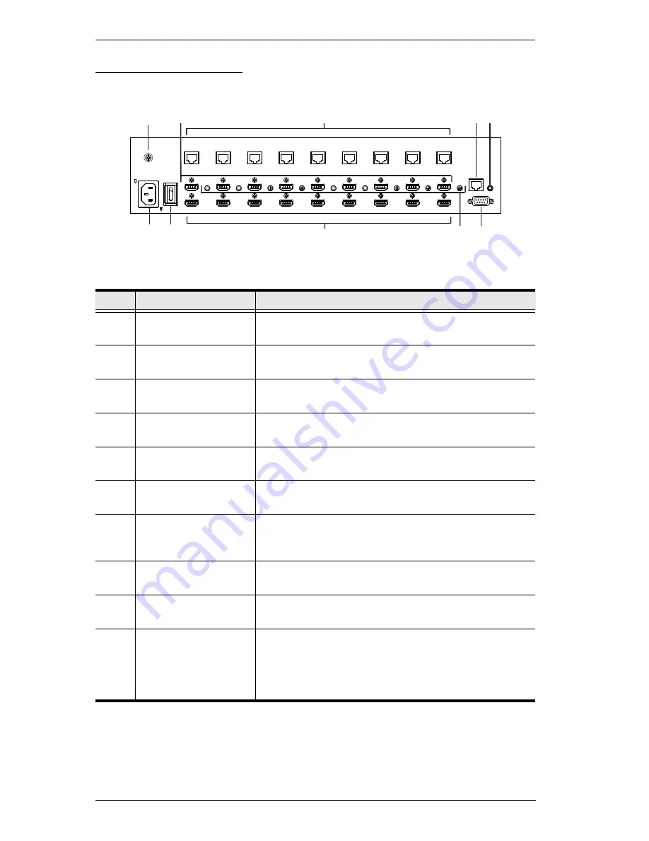
VM3909H Rear View
No.
Component
Description
1
Power Socket
This is a standard 3-pin AC power socket. The power
cord from an AC source plugs in here.
2
Power Switch
This is a standard rocker switch that powers the unit
on and off.
3
Grounding Terminal
The grounding wire attaches here. See
Grounding
,
page 13, for further details.
4
HDMI Input Ports
The cables from your HDMI source devices plug into
these ports.
5
HDBaseT Output
Ports
The cables from your remote HDBaseT display
devices or HDBaseT receivers plug into these ports.
6
HDMI Output Ports
The cables from your local HDMI display devices plug
into these ports.
7
IR Channel Ports
Connect IR receivers / transmitters into the IR Channel
ports for controlling the source and the display from
local or remote locations.
8
IR Port
Connect an IR unit via the 3.5 mm Mini Stereo Jacks.
IR signals are used to control the VM3909H.
9
RS-232 Serial Port
Connect a computer or high-end system controller via
this serial port.
10
Ethernet Port
In order to access the VM3909H’s Browser Graphical
User Interface (GUI), the VM3909H must be
connected to your network. The cable that connects
the VM3909H to your LAN plugs in here. See
Cable
Connection
, page 14, for further details
1
2
3
10
4
5
7 9
8
6
Summary of Contents for VM3404H
Page 1: ...4 x 4 9 x 9 HDMI HDBaseT Lite Matrix Switch VM3404H VM3909H User Manual www aten com ...
Page 25: ...Chapter 2 Hardware Setup 15 Installation Diagram 6 7 1 4 2 9 8 3 2 5 3 1 ...
Page 26: ...VM3404H VM3909H User Manual 16 This Page Intentionally Left Blank ...
Page 48: ...VM3404H VM3909H User Manual 38 This Page Intentionally Left Blank ...
Page 94: ...VM3404H VM3909H User Manual 84 This Page Intentionally Left Blank ...
Page 118: ...VM3404H VM3909H User Manual 108 This Page Intentionally Left Blank ...


