


140-072011 200/202 Series
Page 18 of 24
3.5.
Valve
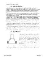
The control valve is an “automatic metering solenoid” valve. While most solenoids operate in either the
fully open or fully closed state, the automatic metering solenoid valve is designed to control flow (see
Figure 3.5). A spring, connected to the plunger assembly, holds a magnetic plunger tightly against an
orifice to shut off flow. The magnetic plunger is surrounded by an electrical coil which, when energized
with electrical current, lifts the plunger off the orifice and allows flow to pass between the orifice and the
plunger seat. Controlling the current through the coil controls the distance between the orifice and the
plunger seat, effectively controlling the flow through the valve. This current is controlled by a feedback
loop that matches the transducer output with the command voltage.
Figure 3.5
Summary of Contents for 8000
Page 2: ......
Page 4: ...ii Atmospheric Technology ...
Page 8: ...2 Atmospheric Technology ...
Page 14: ...8 Atmospheric Technology ...
Page 18: ...12 Atmospheric Technology ...
Page 30: ...24 Atmospheric Technology ...
Page 39: ...Atmospheric Technology 33 Appendix A Schmatics ...
Page 40: ...34 Atmospheric Technology ...
Page 41: ...1 Model 2200V11 Interface Board Schematic 1 sch 7 ...
Page 42: ......
Page 43: ...Model 2200V11 Interface Board Schematic 2 sch 2 7 ...
Page 44: ......
Page 45: ...Model 2200V11 Interface Board Schematic 3 sch 3 7 ...
Page 46: ......
Page 47: ...Model 2200V11 Interface Board Schmatic 4 sch 4 7 ...
Page 48: ......
Page 49: ...Model 2200V11 Interface Board Schematic 5 sch 5 7 ...
Page 50: ......
Page 51: ...Model 2200V11 Interface Board Schematic 6 sch 6 7 ...
Page 52: ......
Page 53: ...Model 2200V11 Interface Board Schematic 7 sch 7 7 ...
Page 54: ......
Page 55: ...Atmospheric Technology 49 Appendix B Manual for Mass Flow Controller ...
Page 56: ......