


30
Atmospheric Technology
Slope = 0.392 x 740 mmHg x 4.1 ccpm = 1.072
292
°
K x 3.8 ccpm
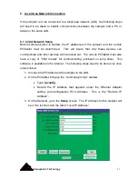
6. Go to the Advanced screen and change the slope to the value calculated in
Step 5. To verify the slope, return to the Manual screen and verify that the
Calibrated Values box is checked when validation the slope. Calculate the
resulting flow using:
Flow = 0.392 x PC x W
TC
The value calculated here should be very close to that shown in the Flow Set
box. It can be trimmed in by adjusting the slope using the following:
New Slope=Old Slope x (calculated flow/desired flow)
Final Note: The MFC zero will drift over time. To compensate for this, the sampler
software auto zeros the MFC prior to sampling. However, a “zero tolerance” error
flag will be displayed whenever the computer needs to zero comp/- 1% of
the range of the MFC. At this point, ATEC recommends that the MFC be
mechanically zeroed to eliminate excessive software compensation which may be a
cause of a MFC malfunction.
Summary of Contents for 8000
Page 2: ......
Page 4: ...ii Atmospheric Technology ...
Page 8: ...2 Atmospheric Technology ...
Page 14: ...8 Atmospheric Technology ...
Page 18: ...12 Atmospheric Technology ...
Page 30: ...24 Atmospheric Technology ...
Page 39: ...Atmospheric Technology 33 Appendix A Schmatics ...
Page 40: ...34 Atmospheric Technology ...
Page 41: ...1 Model 2200V11 Interface Board Schematic 1 sch 7 ...
Page 42: ......
Page 43: ...Model 2200V11 Interface Board Schematic 2 sch 2 7 ...
Page 44: ......
Page 45: ...Model 2200V11 Interface Board Schematic 3 sch 3 7 ...
Page 46: ......
Page 47: ...Model 2200V11 Interface Board Schmatic 4 sch 4 7 ...
Page 48: ......
Page 49: ...Model 2200V11 Interface Board Schematic 5 sch 5 7 ...
Page 50: ......
Page 51: ...Model 2200V11 Interface Board Schematic 6 sch 6 7 ...
Page 52: ......
Page 53: ...Model 2200V11 Interface Board Schematic 7 sch 7 7 ...
Page 54: ......
Page 55: ...Atmospheric Technology 49 Appendix B Manual for Mass Flow Controller ...
Page 56: ......