


28
Atmospheric Technology
converters in the embedded computer do not read negative voltages. Therefore, to
detect MFC negative zero drift, a zero bias needs to be applied to the MFC. Once
the zero is established, the slope is applied to adjust the MFC span to agree with a
certified flow standard referenced to EPA standard conditions of 25
°
C and 760mm
Hg.
It is important to understand that the flow values shown on the Manual Screen can
be referenced to two conditions, either the MFC manufacturer’s reference condition
of 0
°
C and 760 mmHg, or another referenced condition, usually 25
°
C and 760
mmHg. The latter is the condition used during sampling and also displayed in red on
the Manual Screen when the “Calibrated Flow” box is checked.
When it becomes necessary to re-calibrate the MFCs, the flowing procedure should
be followed:
1. Go to the Advanced screen and change the slope for the MFC to be
calibrated to 1.00 and change the intercept value to the negative value of
1.5% of the full MFC range (the MFC range is displayed in the Advanced
Screen). For example, if the MFC has a full range of 2.0 lpm, the intercept
value should be set to -0.030.
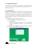
2. Go to the Manual screen and check the box next to “Calibrated Values”. With
no flow, mechanically adjust the MFC zero potentiometer until the screen
display for the flow rate is close to zero (refer to the MFC Operations Manual
in the Appendix for adjustment procedures). There will be some small
oscillations around zero when doing this but try to get it as close as possible.
3. Activate the necessary valve(s) and pump to establish flow rate through the
MFC. Set the MFC flow set value to the nominal flow (the flow rate most
commonly used in sampling). Double press the Set button to apply the new
flow rate set value. If there is no Set button then pressing the Accept button
will set the flow rate.
Summary of Contents for 8000
Page 2: ......
Page 4: ...ii Atmospheric Technology ...
Page 8: ...2 Atmospheric Technology ...
Page 14: ...8 Atmospheric Technology ...
Page 18: ...12 Atmospheric Technology ...
Page 30: ...24 Atmospheric Technology ...
Page 39: ...Atmospheric Technology 33 Appendix A Schmatics ...
Page 40: ...34 Atmospheric Technology ...
Page 41: ...1 Model 2200V11 Interface Board Schematic 1 sch 7 ...
Page 42: ......
Page 43: ...Model 2200V11 Interface Board Schematic 2 sch 2 7 ...
Page 44: ......
Page 45: ...Model 2200V11 Interface Board Schematic 3 sch 3 7 ...
Page 46: ......
Page 47: ...Model 2200V11 Interface Board Schmatic 4 sch 4 7 ...
Page 48: ......
Page 49: ...Model 2200V11 Interface Board Schematic 5 sch 5 7 ...
Page 50: ......
Page 51: ...Model 2200V11 Interface Board Schematic 6 sch 6 7 ...
Page 52: ......
Page 53: ...Model 2200V11 Interface Board Schematic 7 sch 7 7 ...
Page 54: ......
Page 55: ...Atmospheric Technology 49 Appendix B Manual for Mass Flow Controller ...
Page 56: ......